
Spring claw, array spring claw combination plughole contact piece and electric connector

A technology of combining jacks and electrical connectors, applied in conductive connection, clamping/spring connection, connection, etc., can solve the problems of low manufacturing cost, scrapping, twisting and deformation of spring claws, etc., and achieve the effect of reducing labor costs

Inactive Publication Date: 2015-01-28
CHINA AVIATION OPTICAL-ELECTRICAL TECH CO LTD
View PDF10 Cites 13 Cited by
  • Summary
  • Abstract
  • Description
  • Claims
  • Application Information

AI Technical Summary

Problems solved by technology

[0005] The selection of the processing material of the above-mentioned high-elastic claw-type socket and the change of the processing technology of the claw have indeed brought about the effect of reducing the processing cost of the spring claw, thereby reducing the manufacturing cost of the claw-type socket, but through this process There is no corresponding stop structure between the claw and the ring of the manufactured spring claw. When the two spring claws are arranged in an axial array, once the spring claw at the front is pressed, the two spring claws will appear in the axial direction. The problem of upward relative sliding misalignment, so the spring claw is not suitable for axial array use, which will undoubtedly reduce the power of the socket contact, and the gain outweighs the gain
In addition, the ring part of the spring claw processed by the above process does not actually form a closed ring, and its ring part is C-shaped, so the strength is poor. In the process of use, once the insertion force is large and each claw When the internal force is uneven, the claw part of the spring claw will pull the ring part to produce corresponding deformation, which will cause the whole spring claw to be twisted and deformed or even scrapped.
[0006] To sum up, there is currently no spring claw with low manufacturing cost and suitable for axial array arrangement on the market.

Method used


Image

  • Spring claw, array spring claw combination plughole contact piece and electric connector
  • Spring claw, array spring claw combination plughole contact piece and electric connector
  • Spring claw, array spring claw combination plughole contact piece and electric connector

Examples


Embodiment Construction

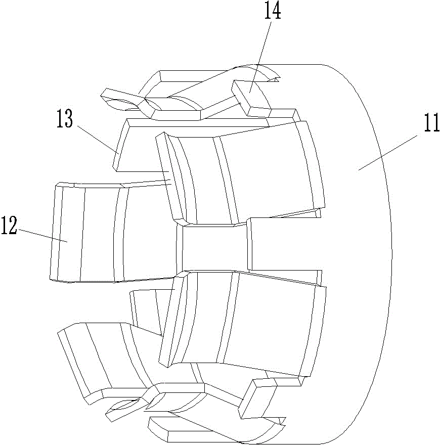
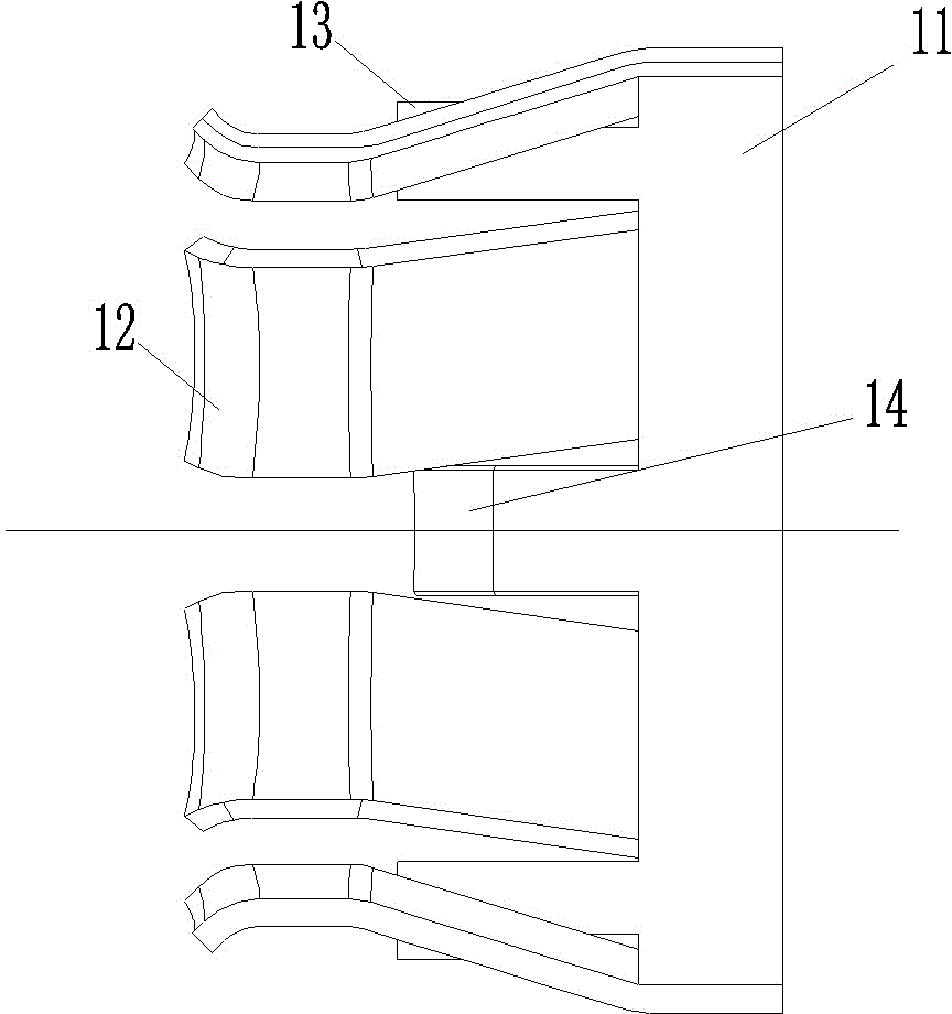
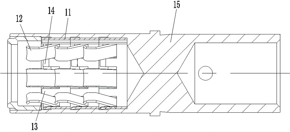
[0024] Examples of spring claws, such as Figure 1-3 As shown, the spring claw is used for the array spring claw combined socket contact, which is wound with a strip material of tin bronze material.

[0025] The spring claw includes a ring portion 11 at the rear end and a claw portion 12 located at the front end of the ring portion 11. The claw portion 12 gradually approaches the axis of the ring portion 11 from back to front. Its specific shape is the prior art and will not be described here. . Different from the prior art, in the spring claw of this embodiment, the claw portions 12 are arranged at intervals around the axis of the ring portion 11 , and a gap is left between two adjacent claw portions. In addition to the claw, the front end of the ring 11 is also provided with a support arm 13 and a thrust barb 14. The support arm 13 extends forward and forms a cantilever structure, and the thrust barb 14 also extends forward and forms a cantilever structure. The difference ...


PUM


Abstract

The invention relates to the field of electric connectors, in particular to a spring claw, an array spring claw combination plughole contact piece and an electric connector. The spring claw is used for the array spring claw combination plughole contact piece, is formed by winding, and comprises a ring part at the rear end and claw parts arranged at the front end of the ring part; the claw parts gradually approach an axis of the ring part from back to front, and are arranged at intervals around the axis of the ring part; supporting arms which overhang forwards and are used for supporting the front corresponding spring claw are arranged at the front end of the ring part; and the supporting arms are located between the corresponding two adjacent claw parts. The spring claw is formed by winding, therefore, the material cost, the labour cost and the like can be lowered compared with a machined spring claw. In addition, the supporting arms are arranged at the front end of the ring part of the spring claw, so that supporting of the front spring claw can be achieved by matching with the rear end of the ring part of the front spring claw by the supporting arms in a using process, and axial array arrangement can be achieved.

Description

technical field [0001] The invention relates to the field of electric connectors, in particular to a spring claw, an array spring claw combined socket contact piece and an electric connector. Background technique [0002] The array spring claw combined socket contact piece is a kind of contact piece that can be used to transmit large current, and it includes a socket and a plurality of car spring claws arranged in the socket. Turning spring claws, as the name suggests, are spring claws made by turning. The turning claw is arranged in the socket along the axial direction of the socket, and it includes an annular ring part at the rear end and a claw part located at the front end of the ring part, between the outer surface of the claw part and the outer surface of the ring part A stepped surface facing forward is formed. After being loaded into the socket, the rear end of the front one of the two adjacent car spring claws is pressed against the stepped surface between the claw...

Claims


Application Information

Patent Timeline
IPC IPC(8): H01R4/48H01R13/187
CPCH01R4/4809H01R13/187
Inventor 王贯民
Owner CHINA AVIATION OPTICAL-ELECTRICAL TECH CO LTD
Features
  • Generate Ideas
  • Intellectual Property
  • Life Sciences
  • Materials
  • Tech Scout
  • Unparalleled Data Quality
  • Higher Quality Content
  • 60% Fewer Hallucinations
Learn More