A switch reluctance motor position detection system and detection method

A switched reluctance motor and detection system technology, applied in control systems, electromechanical devices, AC motor control, etc., can solve the problems of being susceptible to interference, single mode, and the lead-out line length of sine and cosine analog position signals, etc., to achieve reliability High, easy to install, reduce interference effect

Active Publication Date: 2017-01-18
SHANDONG KEHUI POWER AUTOMATION
View PDF4 Cites 0 Cited by
  • Summary
  • Abstract
  • Description
  • Claims
  • Application Information

AI Technical Summary

Problems solved by technology

The two-way sine-cosine position signal switching reluctance motor controller cannot be used directly, and must be converted into a position signal type that the controller can recognize through the position signal adapter board. Usually, the position signal adapter board is installed outside the motor, and the sine-cosine analog The lead-out line of the position signal is long and easily interfered
At present, the position signals required by various switched reluctance motor controllers in the market are not the same. The traditional resolver-to-digital converter (RDC) has a single output position signal mode and is not universal.
[0005] At the same time, in the prior art, the fixing hole of the sensor cover is a waist-shaped hole. When fixing the sensor cover after each disassembly, it is first necessary to pre-fix the sensor cover, and then by detecting the position signal, within a certain rotation adjustment range Rotate the sensor cover inside to determine the initial position of the stator, and finally tighten the sensor cover, the installation and debugging process is more complicated

Method used


Image

  • A switch reluctance motor position detection system and detection method
  • A switch reluctance motor position detection system and detection method
  • A switch reluctance motor position detection system and detection method

Examples


Embodiment Construction

[0039] Figure 1~6 It is the best embodiment of the present invention, below in conjunction with the attached Figure 1~6 The present invention will be further described.

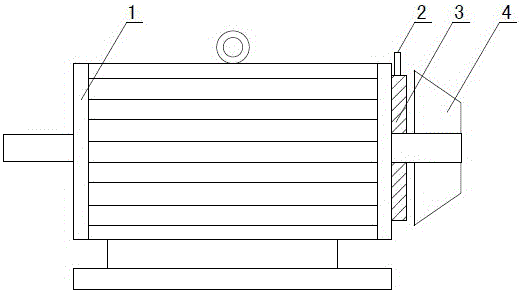
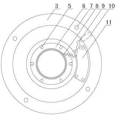
[0040] like figure 1 As shown, a switched reluctance motor position detection system includes a motor stator base 1, a sensor cover 3 is installed at the tail of the motor stator base 1, an extension line 2 is drawn from the side of the sensor cover 3, and the reluctance resolver Located inside the sensor housing 3, the rotor of the reluctance resolver is fixed on the shaft inside the motor. The rotor of the reluctance resolver is installed inside the motor, which has higher reliability when used in harsh environments such as vibration and dust, and can make the motor more beautiful as a whole. The fan 4 is fixed outside the sensor cover 3 .

[0041] In the existing position detection system using a reluctance rotary transformer and a switched reluctance motor, the reluctance rotary transformer is insta...


PUM


Abstract

The invention discloses a position detection system and method for a switch reluctance motor, and belongs to the field of position detection technology for the switch reluctance motor. The position detection system for the switch reluctance motor is characterized in that a magnetic resistance type rotary transformer is installed inside a sensor cover (3), a rotor of the magnetic resistance type rotary transformer is fixed to a shaft inside the motor, a stator (6) of the rotary transformer is fixed to the center of the sensor cover (3), a position signal adapter plate (11) is fixed between the stator (6) of the rotary transformer and the sensor cover (3), a first signal line (8) is led out of a winding of the stator (6) of the rotary transformer and is connected with a control circuit arranged on the position signal adapter plate (11), and a second signal line (9) leading to the outside of the sensor cover (3) is led out of the sensor cover (3) at the same time. Through the position detection system for the switch reluctance motor, the sensor cover does not need to be adjusted when being disassembled or assembled, meanwhile various position signals can be output, and therefore the position detection system for the switch reluctance motor has high adaptability and universality.

Description

technical field [0001] A switched reluctance motor position detection system and a detection method belong to the technical field of switched reluctance motor position detection. Background technique [0002] The switched reluctance motor is a stator and rotor double salient reluctance torque motor. This motor has the advantages of simple structure, reliable performance, small starting current, large starting torque, wide speed range and high efficiency. In order to control the operation of the switched reluctance motor, the controller needs to obtain the position information of the rotor. The position information can be collected by the position sensor, and converted into a usable digital signal and sent to the controller. The position detection of switched reluctance motors has always been a research hotspot. Traditional position detection uses photoelectric or Hall switches to output position signals, and resolvers and photoelectric encoders are also used to detect the ro...

Claims


Application Information

Patent Timeline
Patent Type & Authority Patents(China)
IPC IPC(8): H02P25/08
CPCH02K29/06
Inventor 张鑫贾明全
Owner SHANDONG KEHUI POWER AUTOMATION
Why Eureka
Try Eureka