Magnet yoke for electric induction furnace

An induction furnace and yoke technology, applied in the field of yokes, can solve the problems of long time consumption, many processes, and long welds

Active Publication Date: 2015-01-28
SHANGHAI XINYAN IND EQUIP
View PDF6 Cites 3 Cited by
  • Summary
  • Abstract
  • Description
  • Claims
  • Application Information

AI Technical Summary

Problems solved by technology

Due to many processes, it takes a long time, the welding seam is long, time-consuming and the cooling water is easy to leak
Moreover, the cooling area of ​​the cooling water channel 2 is small, resulting in poor cooling effect

Method used


Image

  • Magnet yoke for electric induction furnace
  • Magnet yoke for electric induction furnace
  • Magnet yoke for electric induction furnace

Examples


Embodiment 1

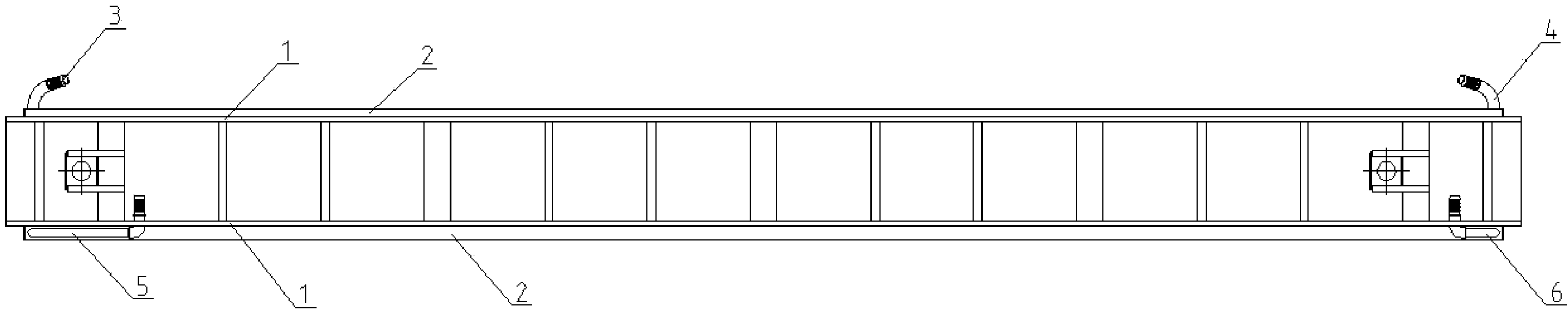
[0034] Figure 4 It is the front view of the induction furnace yoke of the first embodiment.

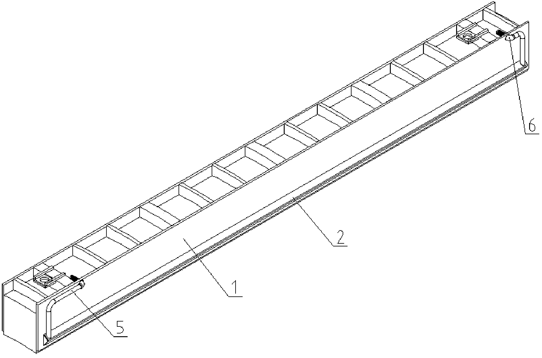
[0035] Figure 5 It is a three-dimensional view of the induction furnace yoke of the first embodiment.

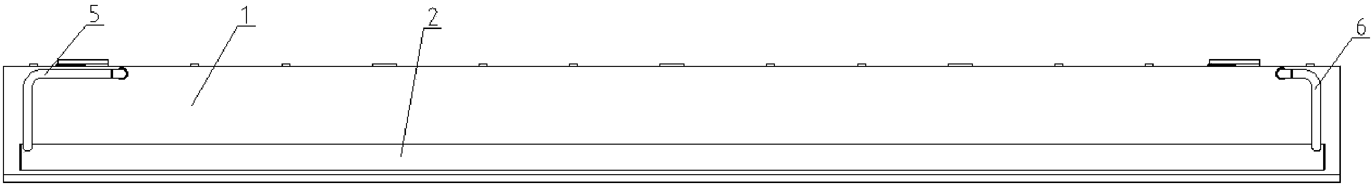
[0036] Image 6 for Figure 4 A-A cutaway view.

[0037] like Figure 4 , Figure 5 and Image 6 As shown, the induction furnace yoke includes: a stacked silicon steel sheet group 50, a back plate 40, two side plates 10, several fixed plates 20, several support plates 30, several fixed installation components 21, water outlets 11, 13 And water inlet 12,14.

[0038] The silicon steel sheet group 50 is formed by stacking multiple silicon steel sheets, and is sandwiched between two side plates 10 .

[0039] The backboard 40 is fixedly connected to the sideboards 10 , and the sideboards 10 are symmetrically fixed on both sides of the backboard 40 . The fixing method can be welded.

[0040] The two side plates 10 are hollow plate structures, providing fluid channels for cool...

Embodiment 2

[0047] Figure 7 It is the front view of the induction furnace yoke of the second embodiment.

[0048] Figure 8 It is a three-dimensional view of the induction furnace yoke of the second embodiment.

[0049] Figure 9 for Figure 7 The B-B section view.

[0050] like Figure 7 , Figure 8 and Figure 9 As shown, the induction furnace yoke includes: a stacked silicon steel sheet group 50, a back plate 40, two side plates 10, several fixed plates 20, several support plates 30, several fixed installation components 21, two communicating pipes 61 , 62, water outlet 15 and water inlet 16.

[0051] The structures and functions of the silicon steel sheet group 50 , the back plate 40 , two side plates 10 , several fixing plates 20 , several support plates 30 , and several fixed installation assemblies 21 in this embodiment are the same as those in the first embodiment.

[0052] Two hollow communication pipes 61, 62 are arranged between the two side plates 10, and at the two ...

Embodiment 3

[0057] Figure 10 It is the front view of the induction furnace yoke of the third embodiment.

[0058] Figure 11 It is a three-dimensional view of the induction furnace yoke of the third embodiment.

[0059] Figure 12 for Figure 10 C-C section view.

[0060] like Figure 10 , Figure 11 and Figure 12As shown, the induction furnace yoke includes: a stacked silicon steel sheet group 50, a back plate 40, two side plates 10, several fixed plates 20, several support plates 30, several fixed installation components 21, two communicating pipes 61 , 62, the intermediate connecting pipe 63, the water outlet 18 and the water inlet 17.

[0061] The structures and functions of the silicon steel sheet group 50 , the back plate 40 , two side plates 10 , several fixing plates 20 , several support plates 30 , and several fixed installation assemblies 21 in this embodiment are the same as those in the first embodiment.

[0062] The hollow communication pipes 61 , 62 and the interm...


PUM


Abstract

The utility model discloses a magnet yoke for an electric induction furnace, and the magnet yoke comprises a stacked silicon steel plate group, a back plate, two side plates, and a plurality of fixed plates. The side plates are hollow plates, and are symmetrically fixed at two sides of the back plate. The stacked silicon steel plate group is disposed between the side plates. The fixed plates are provided with fixed installation holes, and two ends of each fixed plate are respectively in fixed connection with the two side plates. The magnet yoke is advantageous in that a function of cooling and a function of supporting are integrated into one body; the back surface of the magnet yoke is additionally provided with an upper water path and a lower water path, thereby reducing the water leakage points; the magnet yoke achieves the maximization of a water area and a water-flowing cross sectional area and low pressure difference between a water inlet and a water outlet, enhances the cooling effect, and enables the heat dissipation to be more balanced.

Description

technical field [0001] The invention relates to a magnetic yoke, in particular to a magnetic yoke used in an induction electric furnace. Background technique [0002] The induction furnace yoke is an important part in the induction furnace. When the induction coil is energized, the yoke generates a large amount of heat, which must be dissipated in a timely and rapid manner. [0003] figure 1 It is the front view of the traditional induction furnace yoke. [0004] figure 2 It is the bottom view of the traditional induction furnace yoke. [0005] image 3 It is a perspective view of a traditional induction furnace yoke. [0006] like figure 1 , figure 2 and image 3 As shown, the traditional induction furnace yoke includes stainless steel plates 1 on both sides of the silicon steel sheet group, cooling water channel 2, water inlets 3, 5 and water outlets 4, 6. The production method of this structure is to use special tooling, place the stainless steel plate 1, back...

Claims


Application Information

Patent Timeline
Patent Type & Authority Applications(China)
IPC IPC(8): H05B6/02H05K7/20
Inventor 王京骋魏容容平帆
Owner SHANGHAI XINYAN IND EQUIP
Why Eureka
Try Eureka