Gas nuclear reducing valve

A pressure reducing valve and nuclear power technology, applied in the field of pressure reducing valves, can solve the problems of shortening the life of the pressure reducing valve, damage to the compression spring, worsening working conditions, etc., to avoid weakening, reduce leakage points, and facilitate replacement and maintenance.

Pending Publication Date: 2020-07-03
SHANGHAI AVECO VALVE CO LTD +1
View PDF0 Cites 5 Cited by
  • Summary
  • Abstract
  • Description
  • Claims
  • Application Information

AI Technical Summary

Problems solved by technology

Too high or too low post-valve pressure will shorten the life of the pressure reducing valve due to premature damage of the compression spring or cavitation damage of the seat port, and make the pipeline operating conditions worse (such as vibration and noise, etc.)
At present, in the application of nuclear power engineering in the field, there is no domestic manufacturer to manufacture such valves, and they have been relying on imports, which are expensive and inconvenient to maintain.

Method used


Image

  • Gas nuclear reducing valve
  • Gas nuclear reducing valve
  • Gas nuclear reducing valve

Examples


Embodiment Construction

[0034] The technical solutions of the present invention will be clearly and completely described below in conjunction with the accompanying drawings. Apparently, the described embodiments are some of the embodiments of the present invention, rather than all of them. Based on the embodiments of the present invention, all other embodiments obtained by persons of ordinary skill in the art without making creative efforts belong to the protection scope of the present invention.

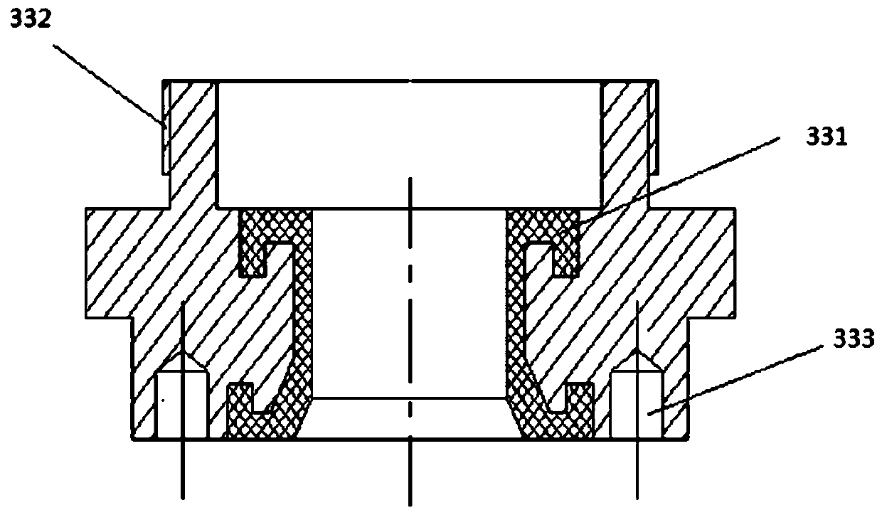
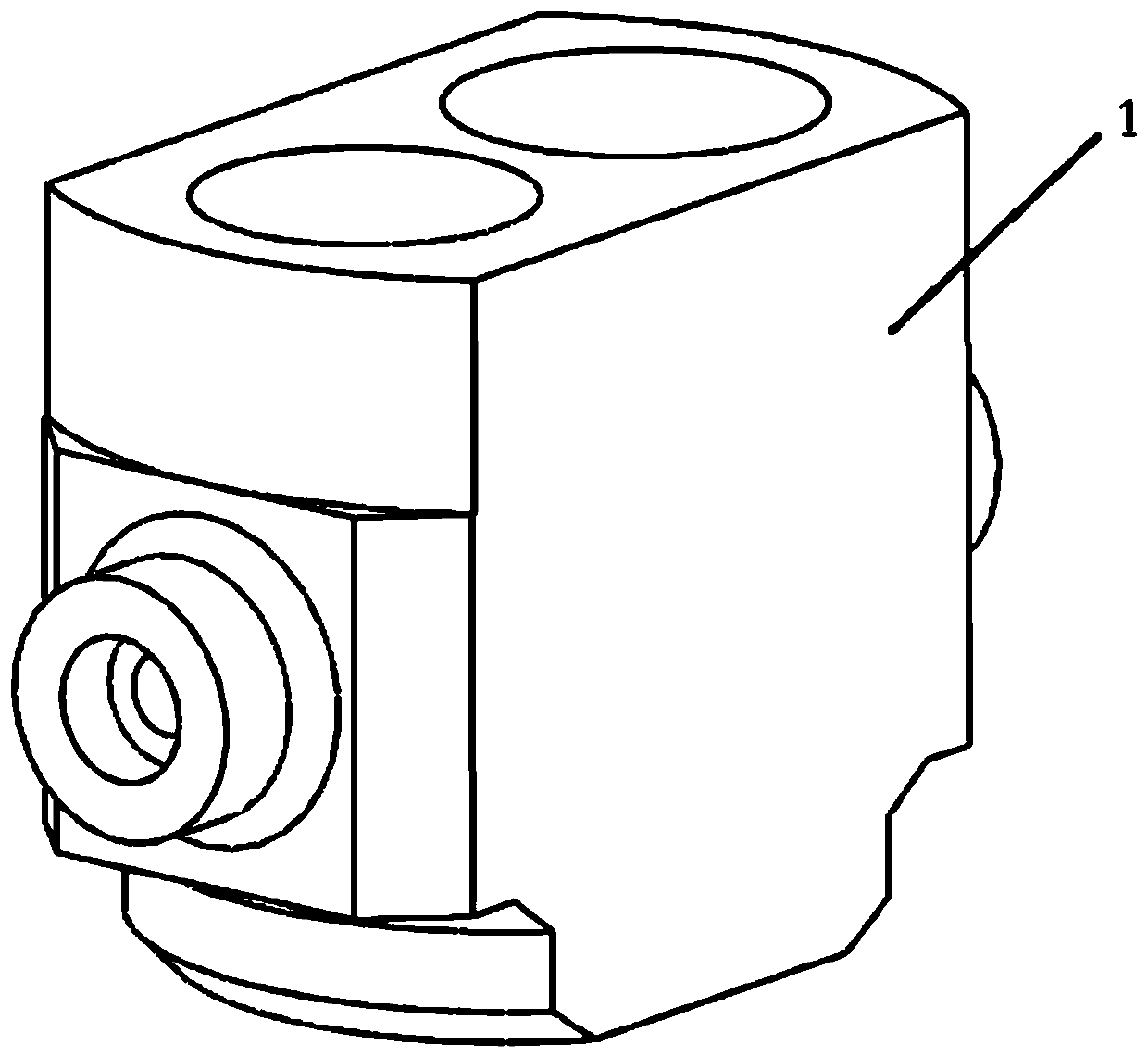
[0035] The invention provides a nuclear power pressure reducing valve for gas, see for details figure 1 , including the valve body, the difference between it and the prior art is that: the valve body 1 is provided with two-stage pressure reducing valves, which are respectively the first stage pressure relief valve unit and the second stage pressure relief valve unit, and one side of the valve body is provided with There is an inlet cavity, and an outlet cavity is provided on the other side. The inlet cavit...


PUM


Abstract

The invention relates to a gas nuclear reducing valve. Two stages of reducing valve units, the first-stage reducing valve unit and the second-stage reducing valve unit, are arranged on a valve body. An inlet cavity is arranged on one side of the valve body, and an outlet cavity is arranged on the other side of the valve body. The inlet cavity communicates with the first-stage reducing valve unit,and the outlet cavity communicates with the second-stage reducing valve unit. A first-stage reducing valve and a second-stage reducing valve are in communication through a runner d. A high-rigidity spring is adopted by the first-stage reducing valve unit, and the high pressure is rapidly roughly adjusted to the intermediate pressure value. A high-precision and low-rigidity spring is adopted by thesecond-stage reducing valve unit, and the outlet pressure is stabilized at the set value. Unit design is adopted by a two-stage reducing device, offline overall assembling can be achieved, and replacement and maintenance are convenient. Due to the fact that horizontal left-and-right arrangement is adopted, the vertical mounting space is saved, and the working condition requirements are met. The reducing valve adopts the flow-to-open type structural design, and the situation that the reducing valve is completely closed in a failure state is avoided.

Description

technical field [0001] The invention relates to the technical field of pressure reducing valves, in particular to a nuclear power pressure reducing valve for gas. Background technique [0002] At present, the pressure reducing valve is widely used and is an indispensable pressure regulating device in various fluid pipeline systems. When the system pipeline is running, the upstream high pressure is generally reduced to the low pressure set point required by the downstream process through the pressure reducing valve, and the outlet pressure is automatically kept stable through the energy of the medium itself. [0003] In the high-pressure gas pipeline of a nuclear power plant of a national project, the working condition requirements are as follows: [0004] Pressure requirements: The inlet pressure range is 27.58~1.38MPa@26.7℃, the outlet pressure requirement is 0.83MPa@26.7℃, and the accuracy requirement is ±5%. [0005] Anti-seismic requirements: anti-seismic grade I three...

Claims


Application Information

Patent Timeline
Patent Type & Authority Applications(China)
IPC IPC(8): F16K17/26F16K1/38F16K27/02G06F30/23
CPCF16K1/385F16K17/26F16K27/0254
Inventor 张正春卢安乐郑张利周强强李聪乐秀辉代琨周旭姜富世胡寒冰包桓铭陈建銮周进超姚玉淋熊春润
Owner SHANGHAI AVECO VALVE CO LTD
Why Eureka
Try Eureka