Environmentally sealed cable breakout assemblies

一种线缆、分支的技术,应用在线缆分支组件远程射频头领域,能够解决增加安装步骤、线缆增加、增加安装成本等问题,达到减少牵引数量、减少数量的效果

Inactive Publication Date: 2015-01-28
HUBERSUHNER AG
View PDF4 Cites 4 Cited by
  • Summary
  • Abstract
  • Description
  • Claims
  • Application Information

AI Technical Summary

Problems solved by technology

This is very expensive, when considering that more cables add to the cost of the installation because the installer is usually charged for each cable pull required, and because the tower owner may be paying by the number of cables, thus increased overall cost
The added weight of the large number of cables and the wind loading issues associated with the construction of multi-conductor cables on antenna towers can be disadvantages
Additionally, using more components introduces the potential for increased installation steps and more maintenance issues associated with more connections

Method used


Image

  • Environmentally sealed cable breakout assemblies
  • Environmentally sealed cable breakout assemblies
  • Environmentally sealed cable breakout assemblies

Examples


Embodiment Construction

[0028] When not otherwise described, similar components are denoted by the same reference numerals.

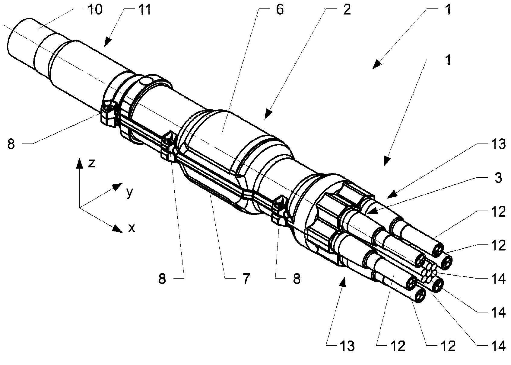
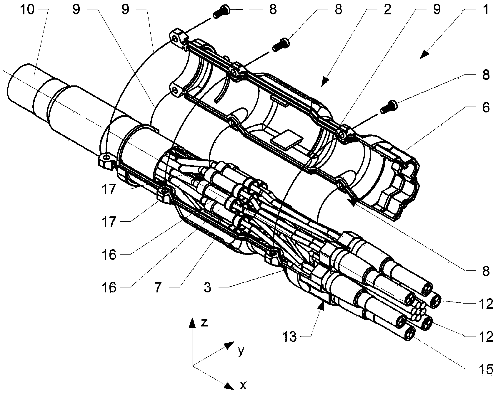
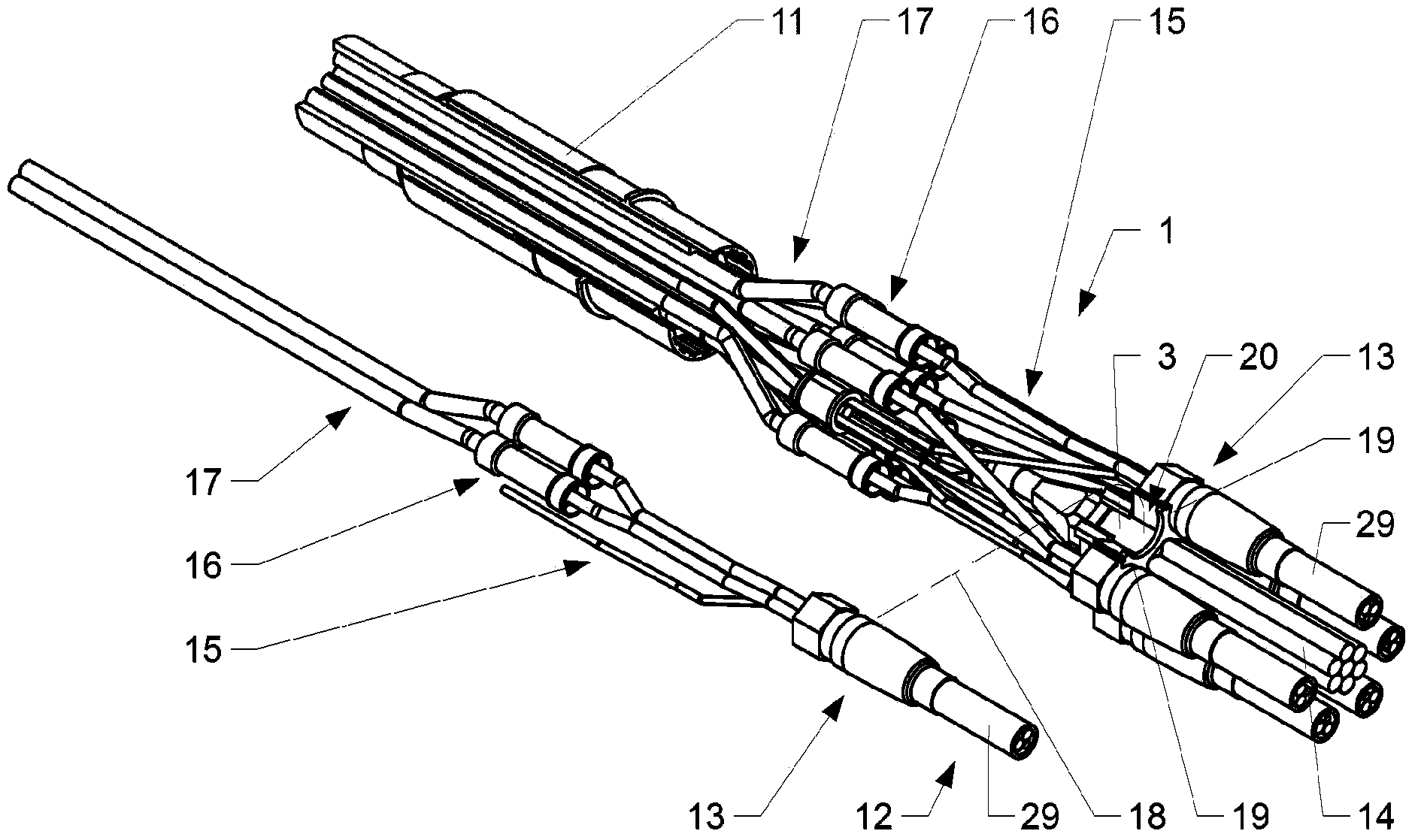
[0029] figure 1 The cable breakout assembly 1 with the breakout housing 2 is shown in perspective. figure 2 The cable breakout assembly 1 is shown with the breakout housing 2 open. image 3 shows no basis figure 2 The cable breakout assembly 1 of the shell 2. Figure 4 The carrier 3 is shown in a perspective view. Figure 5 Details of the housing 4 of the second branch structure 5 are shown.

[0030] The cable branch assembly 1 includes a feed cable 10 interconnected with the branch housing 2 via a first cable gland 11 . The first cable gland 11 is a special type of gland which will be further explained in more detail below. A plurality of power feed subassemblies 12 are interconnected with the branch housing 2 via second cable glands 13 on opposite ends of the branch housing 2 . The second cable glands 13 are arranged in a circumferential manner so as to surround a ...


PUM


Abstract

The invention is directed to a cable breakout assembly (1) comprising a first gland for a feeder cable (10) and several second glands (13) for power feeder subassemblies (12) and an enclosure (2) comprising at least one carrier (3). The at least one carrier is suitable to be interconnected to at least one second gland.

Description

technical field [0001] The invention relates to a remote radio head (RRH) of a cable branch assembly. Background technique [0002] To better facilitate installation and maintenance, radio heads and other equipment used to amplify and transmit signals from antenna towers are traditionally located at the base of the antenna tower. However, this structure is problematic in terms of the signal loss experienced and the power consumption involved. [0003] The so-called Remote Radio Head (RRH) has become an important subsystem of today's new distributed base stations. A remote radio head typically consists of the base station's RF circuitry plus analog-to-digital / digital-to-analog converters and up / down converters. The remote radio head (RRH) may also have processing capabilities for operation and management, and a standardized fiber optic interface for connection to the rest of the base station. Relocating the transmission and amplification components to the top of the antenn...

Claims


Application Information

Patent Timeline
Patent Type & Authority Applications(China)
IPC IPC(8): G02B6/44G02B6/38H02G15/076
CPCG02B6/4471G02B6/3817H02G15/113G02B6/4416H02G15/117Y10T29/49826G02B6/3616H02G15/076
Inventor R·洛夫莱斯R·惠特科姆
Owner HUBERSUHNER AG
Why Eureka
Try Eureka