MIMO communication method, MIMO transmitting device, and MIMO receiving device

a communication method and technology of receiving device, applied in the field of mimo communication method, mimo transmitting device, and mimo receiving device, can solve the problems of inability to apply such 88 mimo communication to small mobile terminals, inability to achieve sufficient effect, and inability to incorporate a plurality of antennas and receive circuits, etc., to achieve the effect of reducing the number of receive antennas and not increasing the number of antennas

Active Publication Date: 2015-10-20
SONY CORP
View PDF4 Cites 0 Cited by
  • Summary
  • Abstract
  • Description
  • Claims
  • Application Information

AI Technical Summary

Benefits of technology

[0010]First, a small housing needs to incorporate N (a plurality of) antennas and receive circuits. That is, the incorporation of a plurality of antennas and receive circuits is against the trend of more compact and lighter design and low power consumption of mobile terminals. In particular, 8×8 MIMO communication, which is assumed in the development of MIMO communication technology, requires up to eight antennas and eight receive circuits; however, applying such 8×8 MIMO communication to small mobile terminals is actually impossible.
[0050]According to the present disclosure, applying multiplexing of codes with different amplitudes to OFDM can reduce the number of receive antennas to one, whereas conventional (N×N) MIMO requires N receive antennas. This enables high-speed MIMO communication without increasing the number of antennas.

Problems solved by technology

That is, the incorporation of a plurality of antennas and receive circuits is against the trend of more compact and lighter design and low power consumption of mobile terminals.
In particular, 8×8 MIMO communication, which is assumed in the development of MIMO communication technology, requires up to eight antennas and eight receive circuits; however, applying such 8×8 MIMO communication to small mobile terminals is actually impossible.
In a case where diversity is not used, the MIMO performance might not sufficiently be exploited, resulting in a problem in which a sufficient effect will not be realized if hardware such as antennas and receive circuits is incorporated.
Third, with the compactness of receivers, an increase in the correlation of communication paths between receive antennas and transmit antennas causes a problem in that the H-matrix described above is not regular and signal separation is not possible.
However, when the technique for changing the planes of polarization of beams is used for actual wireless transmission, radio waves scattered by multiple unspecified scatterers during propagation are combined and received by a receive antenna, which causes the planes of polarization to complexly rotate, resulting in a problem in that the respective systems are considerably difficult to separate.

Method used


Image

  • MIMO communication method, MIMO transmitting device, and MIMO receiving device
  • MIMO communication method, MIMO transmitting device, and MIMO receiving device
  • MIMO communication method, MIMO transmitting device, and MIMO receiving device

Examples


Embodiment Construction

[0065]Examples of embodiments of the present disclosure will be described hereinafter with reference to the accompanying drawings in order below.

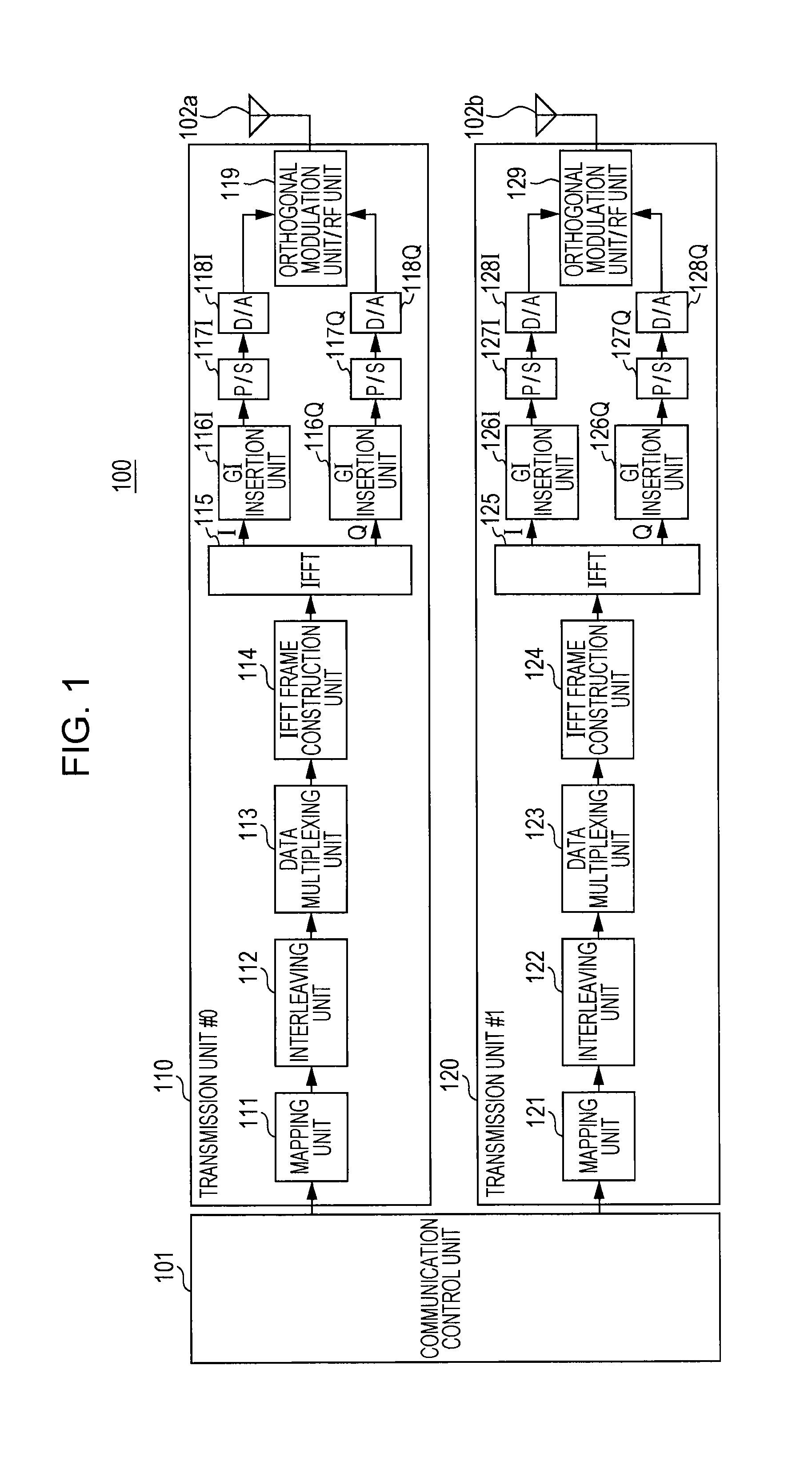
1. Example of configuration of transmitting device according to embodiment (FIG. 1)

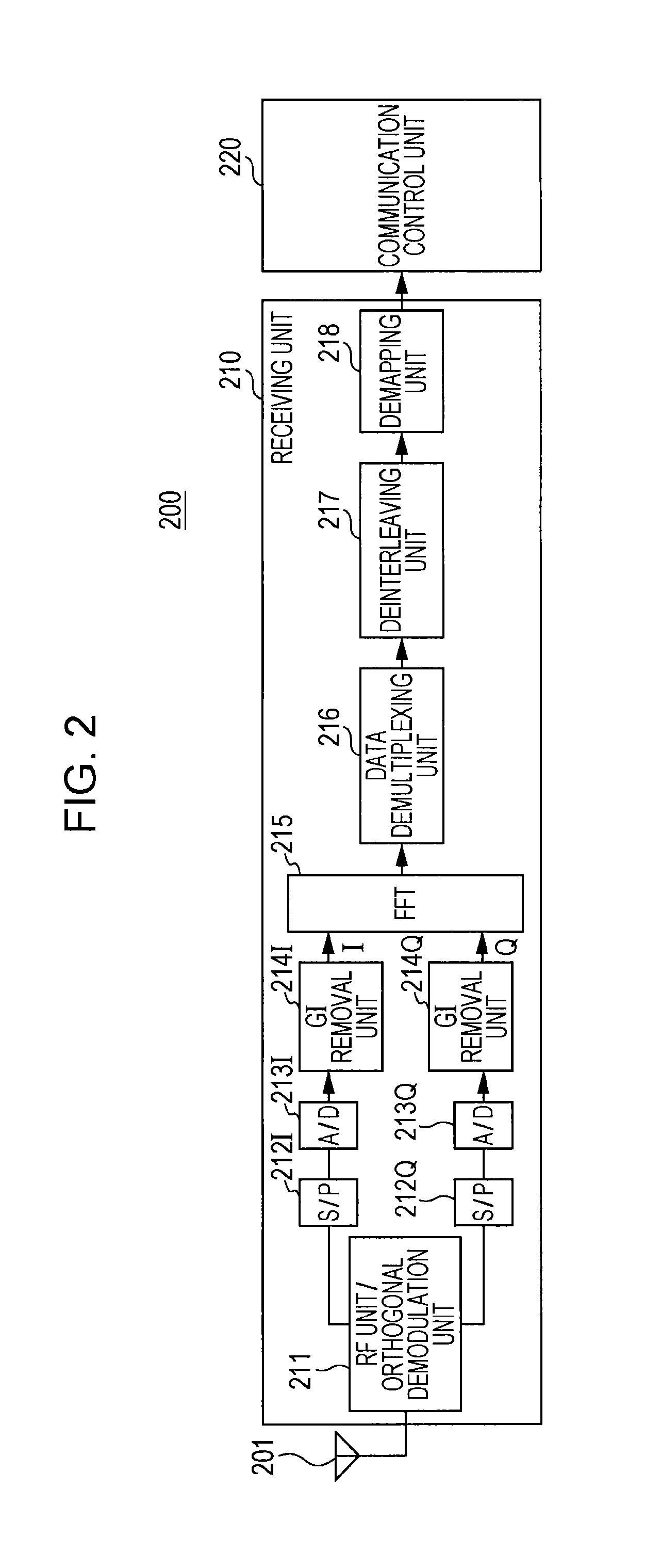
2. Example of configuration of receiving device according to embodiment (FIG. 2)

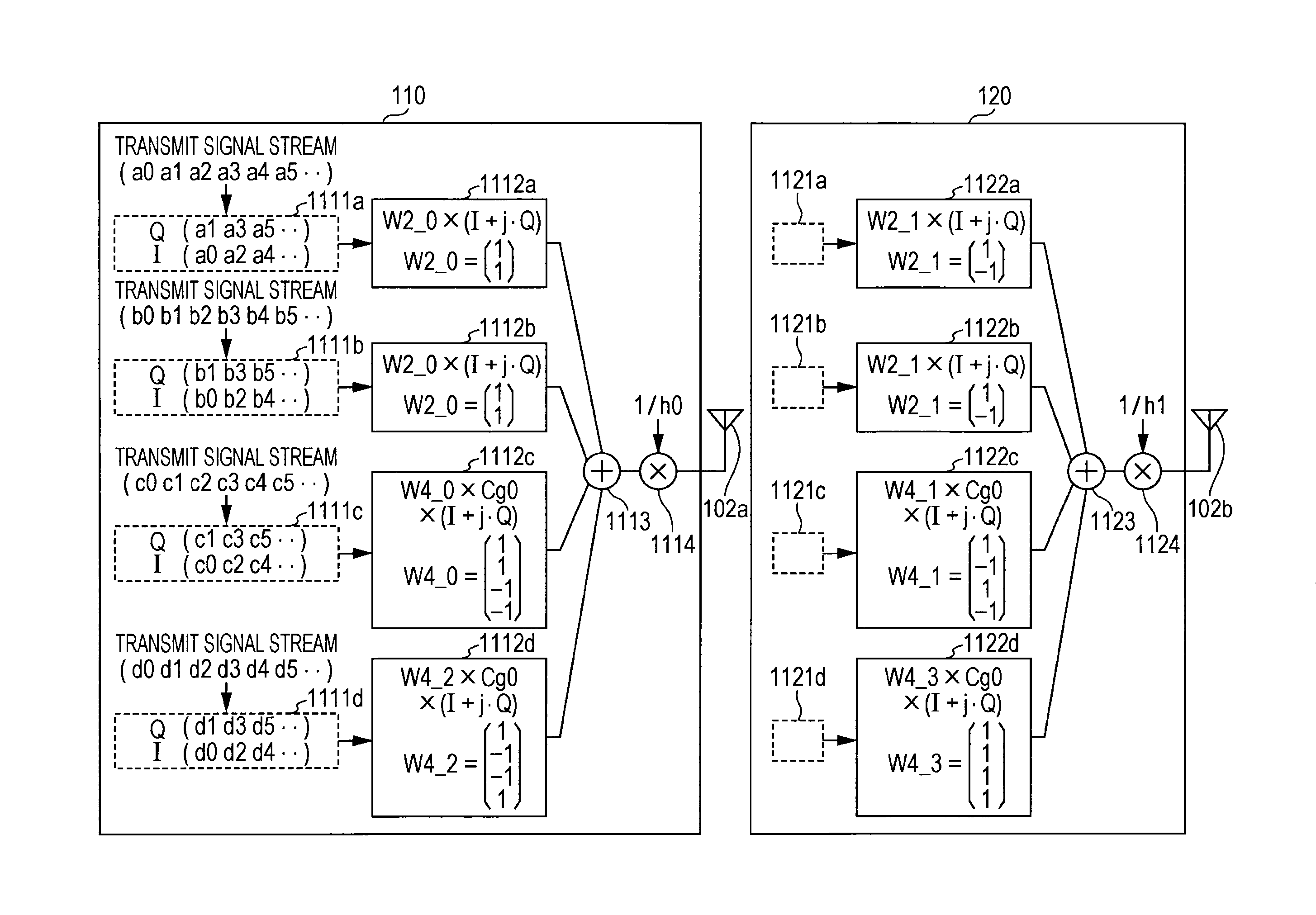
3. Example of data multiplexing unit of transmitting device (FIG. 3)

4. Example of data arrangement (FIG. 4)

5. Example of data separation unit of receiving device (FIG. 5)

6. Example of other embodiment (other example of code multiplexing: FIG. 6)

7. Example of other embodiment (example of using four transmit antennas: FIG. 7)

8. Example of other embodiment (example of using plurality of terminals: FIG. 8)

9. Example of other embodiment (example of taking measures against multipath fading: FIG. 9)

10. Other modified examples

1. Example of Configuration of Transmitting Device according to Embodiment

[0066]FIG. 1 is a block diagram illustrating an example configuration of a transmitting dev...


PUM


Abstract

A first digital signal sequence including I and Q digital signal sequences is obtained, the first digital signal sequence being obtained by multiplying each bit of an I-sequence and a Q-sequence in a digital signal sequence system by a first code among codes constituting n-th order (n is an integer) orthogonal codes. A second digital signal sequence is obtained by multiplying I and Q digital signal sequences by a first coefficient greater than 1, the I and Q digital signal sequences being obtained by multiplying each of the bits in the I-sequence and the Q-sequence in the digital signal sequence system by a first code among codes constituting 2n-th order orthogonal codes. The first digital signal sequence and the second digital signal sequence are added on a bit-by-bit basis to create one digital signal sequence, and the one digital signal sequence is transmitted from a single antenna.

Description

CROSS REFERENCE TO RELATED APPLICATION[0001]The present application claims the benefit of the earlier filing date of U.S. Provisional Patent Application Ser. No. 61 / 835,119 filed on Jun. 14, 2013 and 61 / 776,161 filed Mar. 11, 2013, the contents of each of which is incorporated herein by reference.BACKGROUND[0002]1. Field of the Disclosure[0003]The present disclosure relates to a MIMO communication method that uses MIMO (multiple-input and multiple-output communication), and to a MIMO transmitting device and a MIMO receiving device.[0004]2. Description of Related Art[0005]A MIMO communication scheme has been put into practical use as a technology for increasing communication capacity. This technology is designed to allow different data sequences on N systems to be transmitted using a transmitter having N transmitting units and a receiver having N receiving units, where N is an integer greater than or equal to 2, and reserves a communication capacity that is N times, resulting in a co...

Claims


Application Information

Patent Timeline
Patent Type & Authority Patents(United States)
IPC IPC(8): H04L27/26H04L5/00H04L27/34H04B1/7107H04B7/04
CPCH04L27/265H04B1/71072H04B7/0413H04L5/0021H04L5/0023H04L5/0026H04L27/2602H04L27/2628H04L27/34H04L27/2647H04L27/26524H04L27/26035H04L27/2634
Inventor KUSUNOKI, SHIGEO
Owner SONY CORP
Why Eureka
Try Eureka