Joint part external skeletal fixator

An external fixator and joint technology, applied in the direction of external fixator, fixator, medical science, etc., can solve the problems of complicated fixation operation and large trauma in stent installation, so as to enhance the overall performance, prevent excessive compression, and reduce the possibility of deformation sexual effect

Inactive Publication Date: 2015-02-04
杨震
View PDF5 Cites 2 Cited by
  • Summary
  • Abstract
  • Description
  • Claims
  • Application Information

AI Technical Summary

Problems solved by technology

[0006] The technical problem to be solved by the present invention is: to overcome the technical problems of large trauma and complicated fixation surgery in the prior art, and to provide a kind of joint fixation device that is less traumatic to the installer and can reduce or even eliminate the need for secondary surgery. Fixed structure of bones

Method used


Image

  • Joint part external skeletal fixator
  • Joint part external skeletal fixator
  • Joint part external skeletal fixator

Examples


Embodiment 1

[0041] This product is mainly an external fixator used for postoperative fixation and auxiliary recovery of fractured or dislocated joints. The fixed cable structure for minimally invasive bone surface fixation realizes minimally invasive fixation of joints;

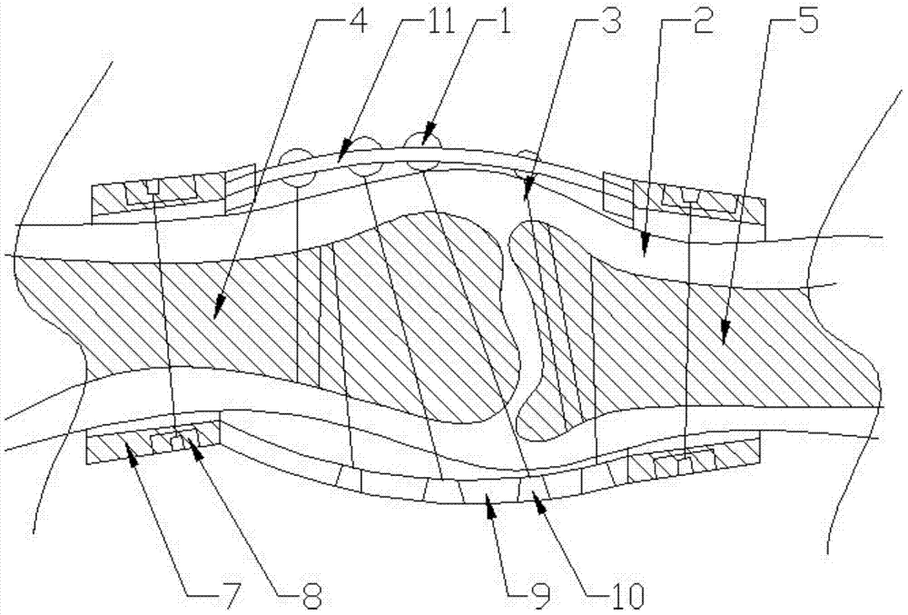
[0042] Such as figure 1 As shown, the product mainly includes two outer frames and fixing rings 7 arranged on both sides of the two outer frames. The relative setting of the outer frame;

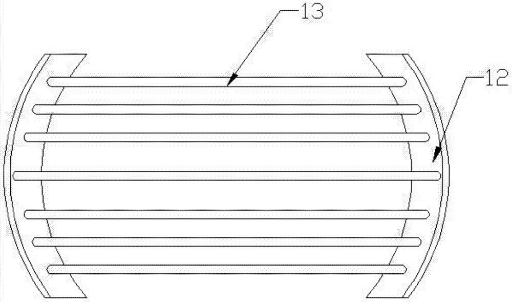
[0043] Such as image 3 , wherein the net-like outer frame 11 includes two splint assemblies 12 and a fixed rod 13, and the shape of the splint assembly is arc-shaped, corresponding to the spherical shape of the joint. One side of the splint assembly is fixedly connected with the fixing ring 7, the splint assembly 12 includes an upper splint and a lower splint, a groove is arranged between the upper splint and the lower splint, and the fixed rod 13 is fixed to the upper splint and the lower splint through the groove between;

[00...

Embodiment 2

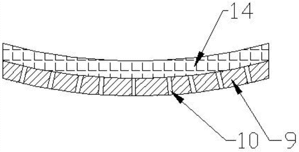
[0058] When immobilizing non-joint structures such as the thigh, e.g. Figure 5 As shown, firstly, the fixing ring 7 made of two cable ties is sleeved on both sides of the epidermis at the bone fracture, the fixing ring 7 is tightened, and then the outer frame 9 of the plate-like structure is fixed to the side of the thigh facing the back, During specific processing, the two can be processed into screw fixation, and then the broken femur (bone C6) is fixed by the fixation cable 3. After the fixation is completed, one end of the fixation cable 3 passes through the fixation hole 10, Fix by the fixed block 1, then install the fixed rod 13 in the middle of the two fixed rings 7 through the upper splint and the lower splint, and set the fixed block 1 on the fixed rod 13 corresponding to the passing position of the fixed cable. The other end of the fixed cable 3 is fixed to the fixed block 1 to realize the fixation of the entire femur; meanwhile, the fixed block 1 and the fixed cabl...


PUM


Abstract

The invention relates to a joint part external skeletal fixator, which comprises an external fixator assembly and a joint fixator, wherein the external fixator assembly is fixedly arranged on the limb part of the body, the joint fixator comprises an outer framework and a plurality of bone surface fixation assemblies arranged on the outer framework, the outer framework is fixedly arranged on the outer part of the body through the external fixator assembly, the outer framework comprises at least two fixing frames, each bone surface fixing assembly comprises a plurality of fixing blocks, fixing cables are arranged among the fixing blocks, the fixing blocks are fixedly arranged on the fixing frames, a support framework formed by at least two fixing cables is arranged between the fixing frames, and the support framework is in contact with the bone surface and realizes the support on the bone.

Description

technical field [0001] The invention relates to an external bone fixator for the joint part, and relates to an external bone fixator for fixing the bones of the joint part by using cables. Background technique [0002] In the process of orthopedic treatment such as fractures, various brackets are often used to penetrate the skin surface after surgery to fix the bones to restore them. After recovery, the brackets are removed through trauma surgery. The whole process requires multiple operations. The trauma to the human muscle and epidermis is relatively large, and the postoperative recovery period is relatively long. At the same time, the traditional brackets cause relatively large compression and trauma to the bones; [0003] In this regard, on the market now, many orthopedic fixators that can reduce the degree of trauma during surgery and reduce the number of operations to a certain extent, and can accelerate healing at the same time, such as the invention of ZL201120537796...

Claims


Application Information

Patent Timeline
Patent Type & Authority Applications(China)
IPC IPC(8): A61B17/60
CPCA61B17/62
Inventor 罗先军
Owner 杨震
Why Eureka
Try Eureka