Inner mirror storing cabinet of storing cavity keeping micro positive force

A micro-positive pressure, storage cavity technology, applied to the field of endoscope storage cabinets, can solve the problems of shortening the service life, unfavorable for water dripping in the endoscope lumen, non-conformity, etc., and achieves increasing the axis length and facilitating the accumulation of water droplets. The effect of falling and air circulation

Active Publication Date: 2015-02-04
LAOKEN MEDICAL TECH
View PDF14 Cites 4 Cited by
  • Summary
  • Abstract
  • Description
  • Claims
  • Application Information

AI Technical Summary

Problems solved by technology

However, none of these techniques can dry the lumen of the endoscope, or even hardly process the inside of the lumen of the endoscope. Internal bacteria are also easy to breed. For this reason, Chinese patent document CN103622754A discloses a kind of endoscope storage cabinet, including a cabinet body, a handle and a shed board. The air filter is equipped with an electric heater in the inner cavity of the air inlet box, an exhaust pipe is arranged on the top of the cabinet, and a suction speed-regulating fan is installed to form a negative pressure in the cabinet, and in the storage cabinet of the cabinet The inner wall is provided with an air nozzle, and the air inlet of the air nozzle communicates with the air outlet of the air compressor, and the inner tube of the endoscope can be inserted into the air nozzle, so that the air compres

Method used


Image

  • Inner mirror storing cabinet of storing cavity keeping micro positive force
  • Inner mirror storing cabinet of storing cavity keeping micro positive force
  • Inner mirror storing cabinet of storing cavity keeping micro positive force

Examples


Embodiment Construction

[0046] specific implementation plan

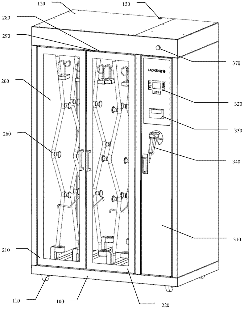
[0047] Such as Figure 1 to Figure 5As shown, the first specific embodiment of the present invention is an endoscope storage cabinet with a storage chamber maintaining a slight positive pressure, including a cabinet body 100, a storage chamber 200, a control chamber 300 and an air duct. The cabinet body 100 is made of carbon steel Or stainless steel and anti-corrosion treatment, there are 4 casters 110 at the bottom of the cabinet 100 for easy movement, and 2 of the casters 110 near the front door have brakes. There is a pipeline outlet 130 on the top, so that the power line or external air source pipeline can be connected, and the joint of the cabinet body 100 and the upper cover 120 with the external circulation air duct 500 is provided with a gasket to prevent external air from entering the external circulation through the gap Leakage of compressed gas in the duct or duct.

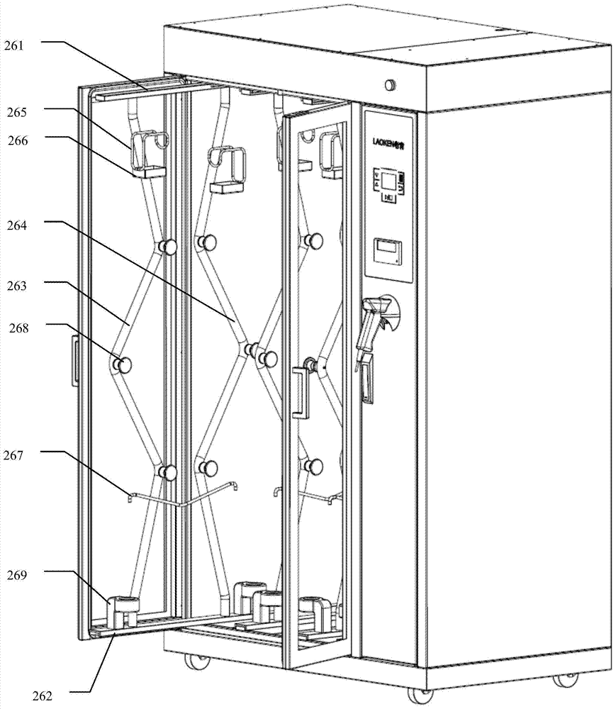
[0048] Storage chamber 200 includes storage chamber left doo...


PUM


Abstract

The invention discloses an inner mirror storing cabinet of a storing cavity keeping a micro positive force. The inner mirror storing cabinet comprises the storing cavity, a control cavity and an air channel, wherein a hanging frame, an inner circulating pipeline joint and an outer circulating air outlet are arranged inside the storing cavity, a control module is arranged inside the control cavity, the air channel comprises an inner circulating air channel and an outer circulating air channel which are respectively connected with the inner circulating pipeline joint and the outer circulating air outlet arranged inside the storing cavity, a pneumatic switch is arranged inside the storing cavity, sealing pieces are arranged at the connecting position and the gap position of a cabinet door of the storing cavity, and the normally closed contact points of the pneumatic switch are in series connection with a power supply circuit of an adjusting draught fan, an air heating module and an air sterile module. When the pressure inside the storing cavity is detected to be lower than a set value, the normally closed contact points of the pneumatic switch are disconnected, the power supply of the adjusting draught fan, the air heating module and the air sterile module is cut off, a certain micro positive force of the interior of the storing cavity relative to the exterior of the cabinet can be kept, and the pollution caused by the fact that the unclean air outside the cabinet flees inside the storing cavity due to the flat pressure or the negative pressure can be avoided.

Description

technical field [0001] The invention relates to a medical storage device, in particular to an endoscope storage cabinet, in particular to an endoscope storage cabinet in which the storage chamber maintains a slightly positive pressure. Background technique [0002] Endoscopes such as gastroscopes, colonoscopes, bronchoscopes, and laryngoscopes are important modern diagnostic and therapeutic instruments. With the development of medical technology, there are more and more types of endoscopes, and the number of endoscopes in various hospitals continues to increase. How to The safe and reliable storage of these valuable endoscopes has become a concern of various hospitals. Driven by market demand, endoscope storage cabinets have emerged as the times require. Today, endoscope storage cabinets have gradually become the endoscope It is a necessary equipment for departments such as operating room, bronchoscopy room, cystoscopy room, ENT department, ENT department, etc. It is used fo...

Claims


Application Information

Patent Timeline
IPC IPC(8): A61B19/02A61L9/20A61L9/22F24F5/00F24F13/28
Inventor 刘俊王川谢小祥刘小平徐鸿张帆
Owner LAOKEN MEDICAL TECH
Why Eureka
Try Eureka