Extruding pulverizer driven by multiple sets of motors

A motor-driven, pulverizer technology, applied in the field of extrusion pulverizers, can solve the problems of uneven force on the shaft, affect the production efficiency of the factory, and consume manpower and material resources, so as to improve the efficiency of restoring production and save manpower and material resources Cost, size and weight reduction effects

Inactive Publication Date: 2015-02-04
安徽华特绿源节能环保科技有限公司
View PDF8 Cites 0 Cited by
  • Summary
  • Abstract
  • Description
  • Claims
  • Application Information

AI Technical Summary

Problems solved by technology

[0003] like figure 2 As shown, since the extrusion pulverizer is a large-tonnage heavy-duty production equipment, a high-power (about 300 kilowatts) motor is usually installed on the above-mentioned extrusion pulverizer, and a pulley is set above the motor and the pulley above the rotating shaft passes through eight belts. connection, so as to drive the rotating shaft to rotate, and then drive the rotor to crush materials; the following two problems will appear in the actual production process: 1. Since the rotating shaft is always under the traction force in one direction, the rotating shaft is always in a state of uneven force during operation , which will produce large vibrations and poor stability, which will have a great impact on production; at the same time, the rotating shaft is prone to shift due to long-term traction in one direction and affects the operation of the rotor, and readjustment requires a lot of manpower and material resources. Inconvenient; 2. Because only one high-power motor is used, it brings a huge load to the motor shaft and the belt. After long-term use, the belt will often fall off or the motor shaft will break. Larger, the weight of the motor reaches several tons, and it takes a lot of time and labor costs to replace the belt once. If the motor needs to be replaced, it will consume more manpower and material resources, which not only affects the production efficiency of the factory, but also creates a large economic burden.

Method used


Image

  • Extruding pulverizer driven by multiple sets of motors
  • Extruding pulverizer driven by multiple sets of motors

Examples


Embodiment 1

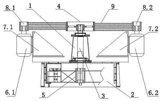
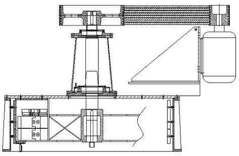
[0013] refer to figure 1 The extrusion pulverizer driven by multiple sets of motors shown includes a body 1 and a crushing chamber 2 connected to the bottom of the body 1. The body 1 is pierced with a main shaft 3 extending into the crushing chamber 2. The body 1 The upper and lower ends of the main shaft 3 are respectively provided with an upper bearing 3.1 and a lower bearing 3.2. The upper end of the main shaft 3 is connected with a large pulley 4, and the lower end of the main shaft 3 is connected with a rotor 5 for crushing mineral materials. The crushing chamber 2 is equipped with the motor mount 7.1 of installing left motor 6.1 and the motor mount 7.2 of installing right motor 6.2 symmetrically with main shaft 3 on 2, the power of left motor 6.1 and right motor 6.2 is 150 kilowatts, and all rotates along the same direction, left The shaft upper end of motor 6.1 and right motor 6.2 is respectively connected with left belt pulley 8.1 and right belt pulley 8.2, links to e...

Embodiment 2

[0015] As the second embodiment of the present invention, no drawings are provided, and its basic structure is the same as that of Embodiment 1, the difference is that there are four motor racks on the crushing chamber, each of which is equipped with a motor rack with the same power and steering. The four motors are arranged in a cross shape with the main shaft as the center, and the large pulleys are respectively connected to the four small pulleys through staggered belt transmissions. The power of the four motors is equivalent to the power of the original large motor, which is enough to support the normal operation of the extrusion pulverizer. At the same time, they are arranged in a cross shape, and act together on the main shaft from four directions to ensure that the main shaft is evenly stressed and will not be biased. It is also more convenient to disassemble and repair.

Embodiment 3

[0017] As the third embodiment of the present invention, no drawings are provided, and its basic structure is the same as that of Embodiment 1, the difference is that three motor frames are arranged on the crushing cavity, and a motor with the same power and steering is installed on each of them. , the three motors are arranged in an equilateral triangle with the main shaft as the center, and the large pulleys are respectively connected to the three small pulleys through staggered belt transmission. The power of the three motors is equivalent to the power of the original large motor, which is enough to support the normal operation of the extrusion pulverizer. At the same time, the arrangement of the equilateral triangle makes the spindle evenly loaded and more stable and reliable, and it is also more convenient to disassemble and repair.


PUM


Abstract

The invention relates to an extruding pulverizer driven by multiple sets of motors. The extruding pulverizer comprises a pulverizer body and a crushing cavity connected with the downside of the pulverizer body, a main shaft extending into the crushing cavity is connected into the pulverizer body in a penetrating manner, the upper end and lower end of the pulverizer body are respectively provided with an upper bearing and a lower bearing of the main shaft, the upper end of the main shaft is connected with a large belt pulley, the lower end of the main shaft is connected with a rotor used for crushing a mineral substance, at least two motor racks are arranged on the crushing cavity by using the main shaft as a center, and are respectively provide with a motor, the motors are mutually symmetric and are same in power and rotating direction, small belt pulleys are arranged at the upper ends of shafts of the motors, and the large belt pulleys and the small belt pulleys are in transmission connection by means of belts which are arranged in a staggered manner. The extruding pulverizer is simple in structure, convenient to maintain, and relatively low in cost; failures are easily caused; the production efficiency is ensured, and a large quantity of manpower and material resource cost is saved.

Description

technical field [0001] The invention relates to an extrusion pulverizer, in particular to an extrusion pulverizer driven by multiple sets of motors. Background technique [0002] Extrusion mills currently on the market for crushing mineral materials are mainly used for crushing medium-hard materials such as limestone, gypsum, and dolomite. There is an extrusion mill for crushing mineral materials. Its working principle Firstly, pour large materials into the crushing chamber of the machine body, and use the rotating shaft to drive the rotor to rotate and collide with the crushed materials. Under the extrusion of the hard hammer head, it is crushed into fine particles, and many of the smaller material particles and powder have already passed through the through holes on the liner and the bottom liner and flowed to the discharge channel under the pressure of the hard hammer head. And fall into the discharge hopper; in addition, the fine granular materials that have not passed ...

Claims


Application Information

Patent Timeline
IPC IPC(8): B02C13/30
CPCB02C13/30
Inventor 董大川易传金杨国栋
Owner 安徽华特绿源节能环保科技有限公司
Why Eureka
Try Eureka