Special side-sliding pressing pin for pattern machine

A technology of pattern machine and presser foot, which is applied in the direction of floral stitch sewing machine, cloth pressing mechanism, sewing machine components, etc., can solve the problems that the presser foot template cannot be kept stable, the lifting mechanism is heavy and other problems, achieve good sewing effect, reduce Process, the effect of improving sewing efficiency

Inactive Publication Date: 2015-02-04
ZHEJIANG ZOJE SEWING MACHINE +2
View PDF7 Cites 5 Cited by
  • Summary
  • Abstract
  • Description
  • Claims
  • Application Information

AI Technical Summary

Problems solved by technology

[0004] The forward and backward sliding presser foot template of the sewing machine provided by the above patent moves the presser foot template forward and backward through the cylinder, and the whole base pla...

Method used


Image

  • Special side-sliding pressing pin for pattern machine
  • Special side-sliding pressing pin for pattern machine
  • Special side-sliding pressing pin for pattern machine

Examples


Embodiment 1

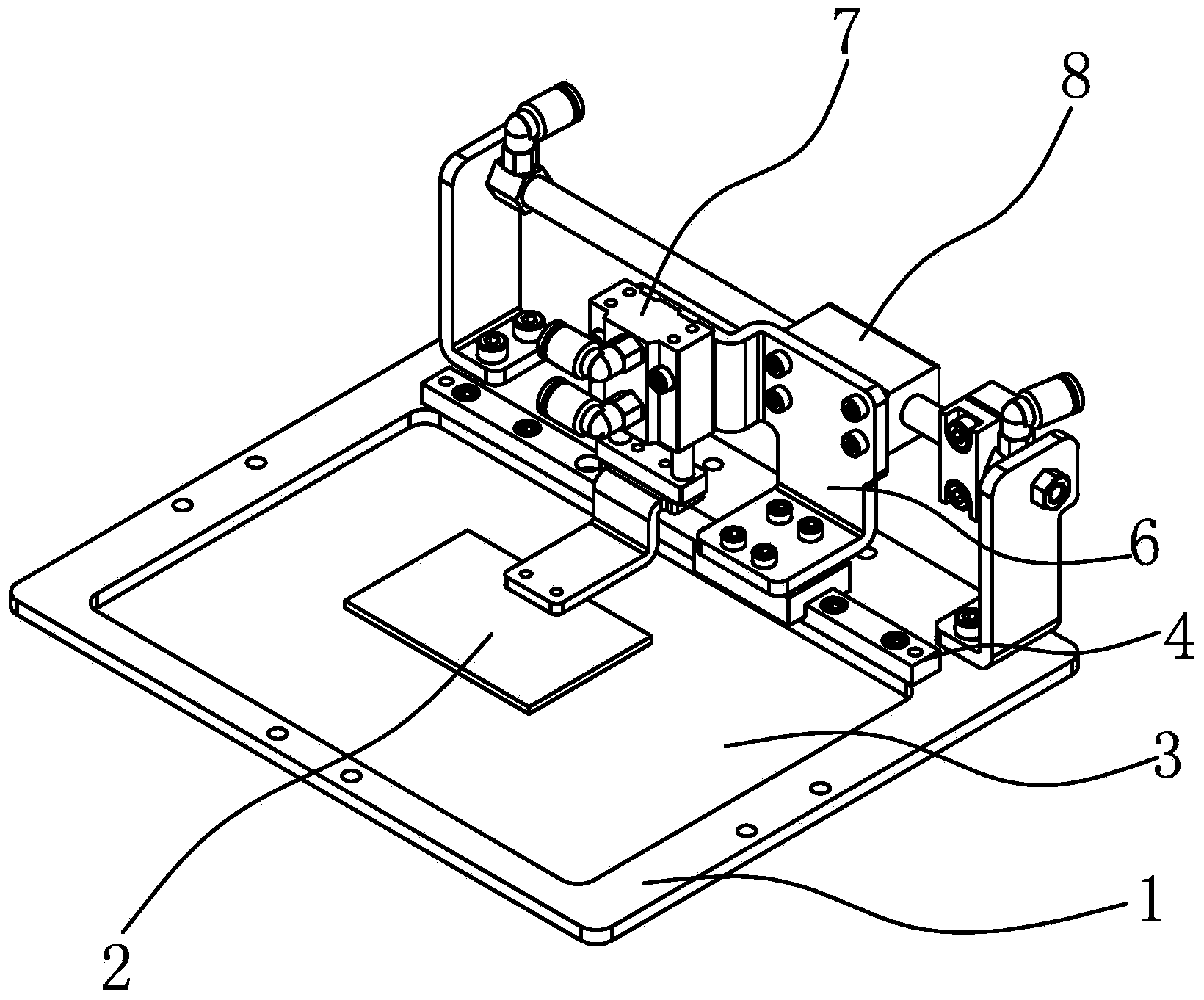
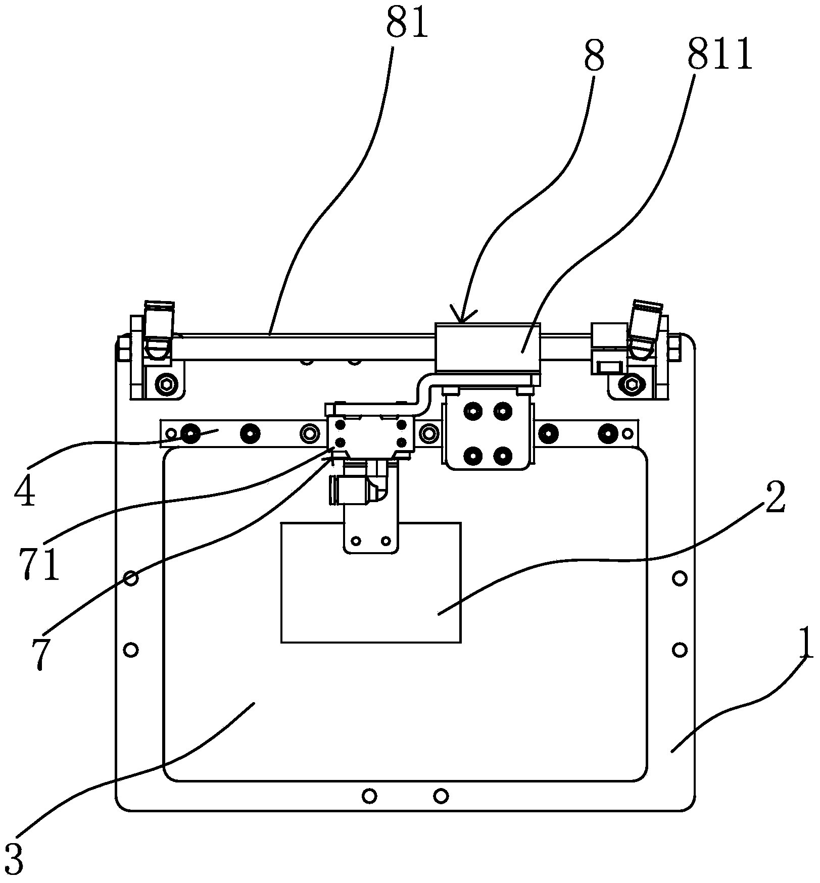
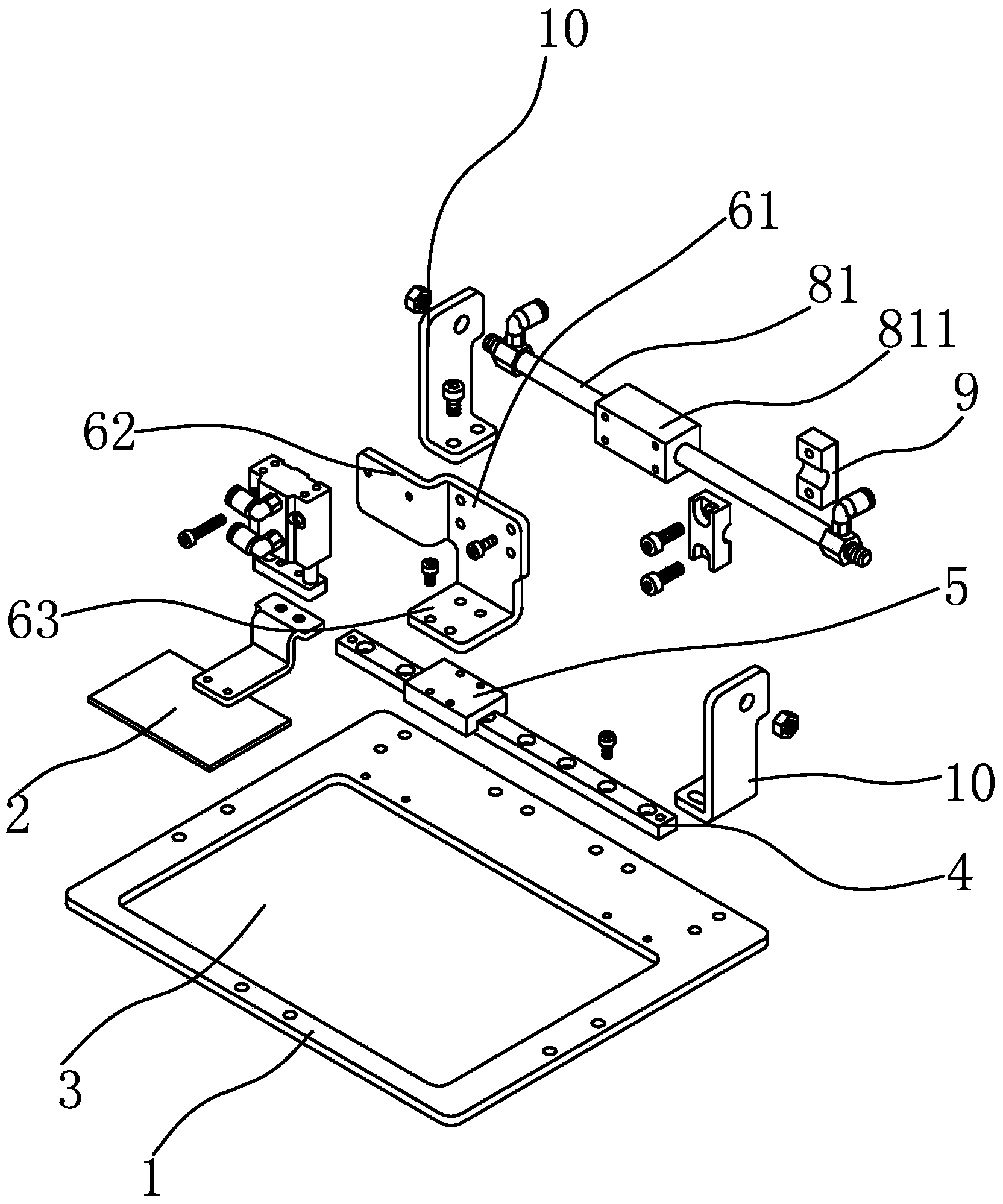
[0025] Such as figure 1 , figure 2 and image 3 As shown, the side-slip special presser foot includes a presser frame 1 and a presser template 2, the presser frame 1 is square, the middle part of the presser frame 1 has a square working through hole 3, and one side of the presser frame 1 is along the side The length direction is fixedly provided with a slide rail 4, the slide rail 4 is slidably connected with a connecting plate 6, and the connecting plate 6 is fixedly provided with a lifting mechanism 7 capable of driving the binder template 2 to move up and down. The lifting mechanism 7 includes a cylinder 71, and the cylinder 71 Fixed on the connecting plate 6 with the piston rod facing down, the pressing template 2 is screwed with the piston rod of the cylinder 71, the pressing template 2 is connected with the lifting mechanism 7, and the pressing template 2 can extend into the pressing frame 1 In the area of ​​the operation through hole 3, the pressing template 2 moves ...

Embodiment 2

[0031] This embodiment is substantially the same as Embodiment 1, the difference is that the driving member 8 in this embodiment includes a lead screw and a screw nut, the screw nut is screwed on the lead screw, the connecting plate 6 is fixedly connected with the screw nut, and the lead screw It is connected with a motor that can drive it to rotate, and the motor rotates forward and reversely to drive the lead screw to rotate, and the movement of the screw nut is driven by the thread to change the position of the pressing template 2 to achieve the same purpose.


PUM


Abstract

The invention provides a special side-sliding pressing pin for a pattern machine, belongs to the technical field of sewing devices, and solves the technical problems of poor material pressing effect, poor convenience and the like of an existing special side-sliding pressing pin. The special side-sliding pressing pin comprises a material pressing frame and a material pressing template, wherein an operation through hole capable of extending into the material pressing template and a sewing needle is formed in the middle of the material pressing frame; a sliding rail is fixedly arranged at one side of the material pressing frame along the length direction of the side edge; the sliding rail is connected with a connection plate in a sliding manner; a lifting mechanism capable of driving the material pressing template to move up and down is fixedly arranged on the connection plate; the material pressing template is connected with the lifting mechanism; the bottom surface of the material pressing template can be level to the bottom surface of the material pressing frame; the special side-sliding pressing pin also comprises a driving piece which can drive the connection plate to move on the sliding rail along the length direction of the sliding rail. The driving piece in the pressing pin can drive the material pressing template to move on the sliding rail, so that the position of the material pressing template in a sewing area can be changed, the condition that the whole sewing can be finished once during sewing can be ensured, and further the sewing efficiency and the sewing effect can be improved.

Description

technical field [0001] The invention belongs to the technical field of sewing equipment, and relates to a presser foot structure of a pattern machine, in particular to a side-slip special presser foot of a pattern machine. Background technique [0002] The electronic pattern machine is the most advanced machine used in the handbag factory, shoe factory, luggage factory, garment factory, leather goods factory and furniture factory. It can realize the traditional manual pattern with high speed and high efficiency, and can also realize The requirements of "multi-level, multi-functional, uniform and perfect" cannot be achieved by hand-made patterns. It is an electromechanical product that embodies a variety of high-tech. In sewing equipment, the presser foot can press the product to be processed to avoid wrinkling, so that the product can be processed efficiently and accurately, especially the pattern sewing of the electronic pattern machine. The quality of the presser foot pre...

Claims


Application Information

Patent Timeline
IPC IPC(8): D05B29/08D05B29/02D05B9/00
CPCD05B29/08D05B9/00D05B29/02
Inventor 严海军孙灵君杨培楼俏军
Owner ZHEJIANG ZOJE SEWING MACHINE
Why Eureka
Try Eureka