Mechanical driver for fixed-diameter orifice pipelines

A mechanical drive, sizing hole technology, applied in mechanical equipment, special pipes, pipe components, etc., can solve the problems of no special design and the way of walking is not stable enough.

Inactive Publication Date: 2015-02-04
HARBIN ENG UNIV +1
View PDF4 Cites 5 Cited by
  • Summary
  • Abstract
  • Description
  • Claims
  • Application Information

AI Technical Summary

Problems solved by technology

In terms of patent applications, the patent application number CN200510100462.1 is titled "A Mechanical Driving Method and a Driving Device Using the Method". The push rod at the front end of the crank-slider mechanism swings to realize the output transmission of power, there is no special design in positioning, and the way of walking is not stable enough

Method used


Image

  • Mechanical driver for fixed-diameter orifice pipelines
  • Mechanical driver for fixed-diameter orifice pipelines
  • Mechanical driver for fixed-diameter orifice pipelines

Examples


Embodiment Construction

[0013] The present invention is described in more detail below in conjunction with accompanying drawing example:

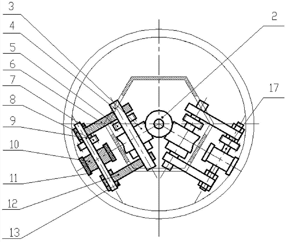
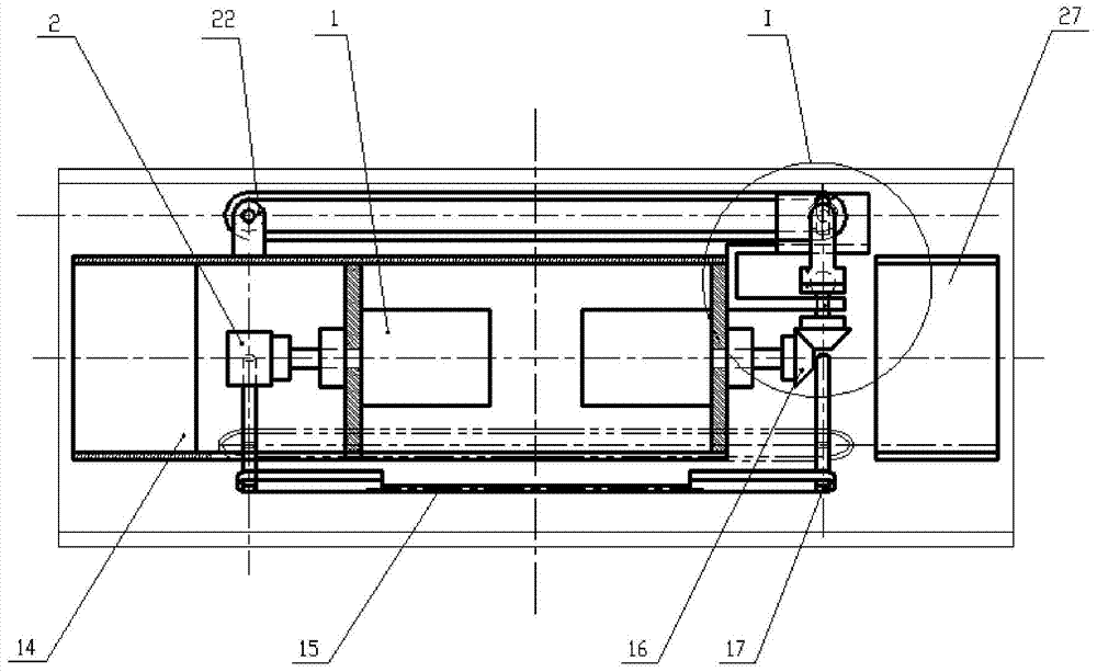
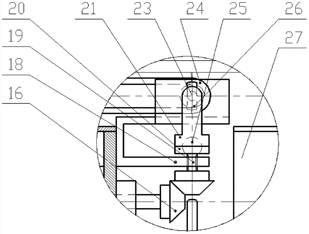
[0014] combine Figure 1~4 The main components of the drive device of the present invention include a DC motor 1, a worm rod 2, a turbine 3, a turbine shaft 4, a drive pulley 5, a first drive wheel bracket 6, a first tensioning joint 7, a driven pulley 8, Drive wheel shaft 9, drive wheel 10, first track 11, second drive wheel support 12, second tension connector 13, detector 14, track tension adjustment lever 15, bevel gear 16, driven wheel shaft 17, screw connection Seat 18, spiral ball head section 19, ball head gland 20, ball head swivel seat 21, support frame 22, support wheel shaft 23, support track 24, spiral ball head section 25, slideway 26, electric control Case 27, shaft end cover 28, support wheel 29.

[0015] Before the driving device is powered on, it is necessary to adjust the axial tightness of the track. The track tensioning adjusting rod 15 is ...


PUM


Abstract

The purpose of the invention is to provide a mechanical driver for fixed-diameter orifice pipelines, which comprises a housing, a first motor, a worm, a first traveling mechanism and a second traveling mechanism, the first motor is mounted in the housing, the worm is connected with the first motor, the first traveling mechanism comprises a worm gear, a worm gear shaft, a first driving wheel support, a second driving wheel support, a driving wheel, a driven wheel, a driving belt pulley, a driven belt pulley and a driving wheel shaft, both the worm gear shaft and the driving wheel shaft are mounted on the first driving wheel support and the second driving wheel support, the worm gear and the driving belt pulley are mounted on the worm gear shaft, the driving wheel and the driven belt pulley are mounted on the driving wheel shaft, the worm gear cooperates with the worm, the driving belt pulley is engaged with the driven belt pulley, the driving wheel and the driven wheel are respectively located at the front end and rear end of the housing, a track which is in contact with the inner wall of a pipeline is wound on the driving wheel and the driven wheel, and the second traveling mechanism has the same structure as the first traveling mechanism. The mechanical driver has the characteristics of miniaturization, light weight, equipment modularization, multiple purposes and the like.

Description

technical field [0001] The invention relates to a driving device, in particular to a pipeline driving device. Background technique [0002] Usually, the pipeline driving device is used to connect some high-precision measuring equipment or equipment used for pipeline maintenance, etc., to provide greater power for the working equipment. Foreign countries started earlier in pipeline robots and achieved more results. For example, DENSO Corporation of Japan has developed a micro-pipeline robot with laminated piezoelectric actuators, but its driving force is small, heat generation is large, and power consumption is high. The double piezoelectric film microrobot developed by Shanghai University can reach a speed of 18mm / s, but the maximum load capacity is only 50g. In terms of patent applications, the patent application number CN200510100462.1 is titled "A Mechanical Driving Method and a Driving Device Using the Method". The push rod at the front end of the crank-slider mechani...

Claims


Application Information

Patent Timeline
Patent Type & Authority Applications(China)
IPC IPC(8): F16L55/30F16L101/00F16L101/30
CPCF16L55/30F16L2101/00F16L2101/30
Inventor 张忠林周辉李永涛赵飞周雪鹏
Owner HARBIN ENG UNIV
Why Eureka
Try Eureka