
Optical cable for rail transit

A technology for rail transit and optical cables, applied in the field of optical cables for rail transit, can solve the problems of affecting communication performance, increasing the weight of metal reinforcements, and being easily affected by lightning, so as to reduce self weight, facilitate laying and installation, and strengthen water blocking effect Effect

Inactive Publication Date: 2015-02-04
BEIJING HENGTONG SIBO COMM TECH CO LTD
View PDF6 Cites 11 Cited by
  • Summary
  • Abstract
  • Description
  • Claims
  • Application Information

AI Technical Summary

Problems solved by technology

For example, the cable tie of the fixed structure affects the shape of the loose tube, the metal reinforcement increases its own weight and is easily affected by lightning, and the use of unsupported components makes the optical fiber easy to be affected by the optical fiber when it is pressed by external force, thereby affecting the communication performance.

Method used


Image

  • Optical cable for rail transit

Examples


Embodiment Construction

[0010] The present invention will be further described below in conjunction with the embodiments and accompanying drawings.

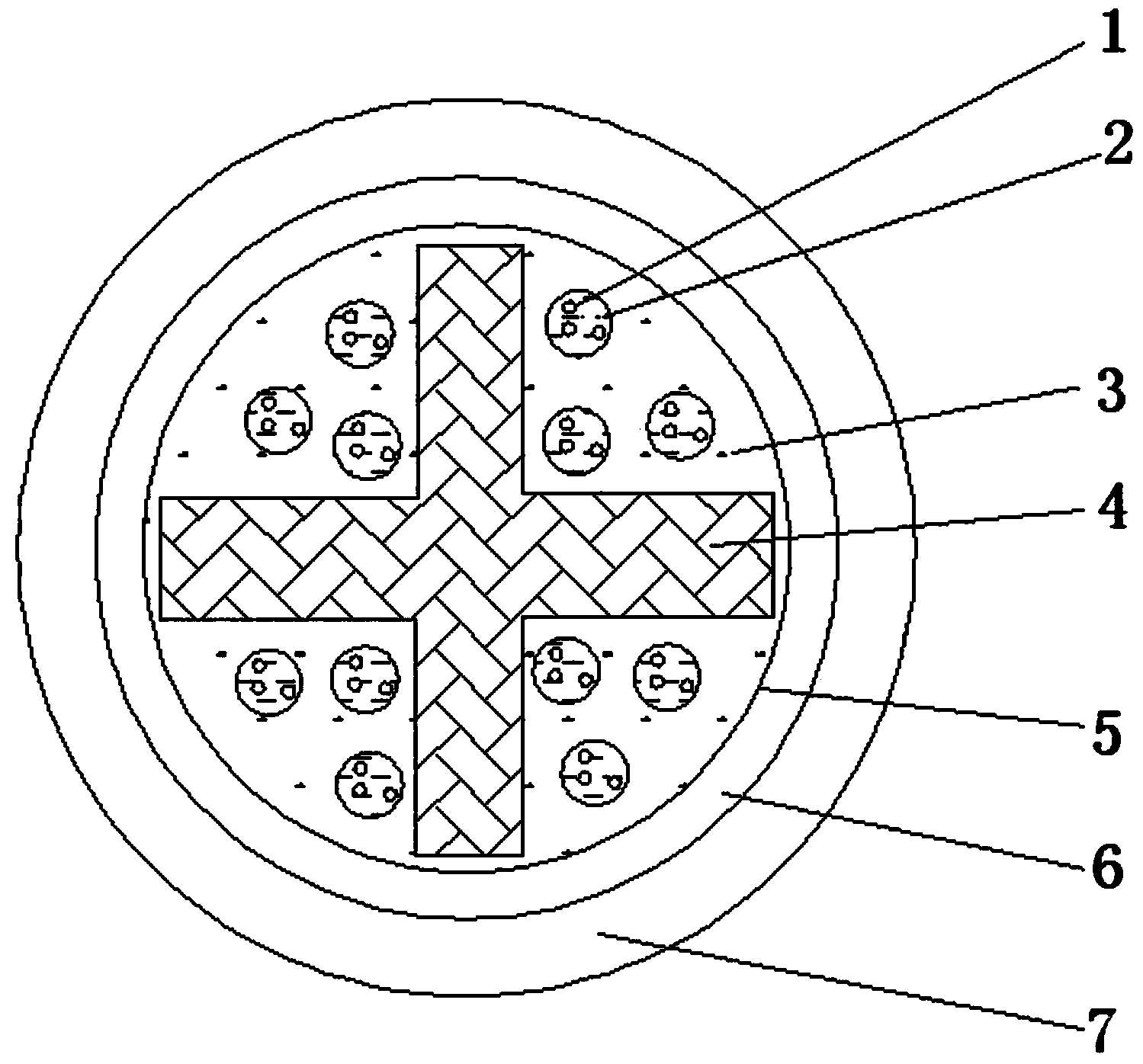
[0011] figure 1 It is a schematic cross-sectional structure diagram of an optical cable for rail transit. The optical cable for rail transit includes an optical fiber 1, a loose tube 2, a water-blocking wire 3, a skeleton 4, a yarn binding 5, an aluminum-plastic composite tape layer 6 and an outer sheath 7. The optical fiber 1 is placed directly in the loose tube 2, and the fiber paste is filled between the loose tube 2 and the optical fiber 1 to form an optical fiber core. The cross-section of the skeleton 4 of the composite carbon fiber is a cross-shaped structure, and the cross-shaped structure of the skeleton 4 divides the surroundings of the skeleton into 4 spaces, and 3 optical fiber cores are arranged in each space around the skeleton 4 . Fill the space between the optical fiber cores and between the optical fiber core and the skeleton 4 with w...


PUM


Abstract

The invention discloses an optical cable for rail transit, belonging to the technical field of optical cables. An optical fiber is straightly placed in a loose sleeve, and fiber paste is filled between the loose sleeve and the optical fiber to combine an optical fiber core. The cross section of a framework is of a cross-shaped structure, the cross-shaped structure of the framework is used for partitioning the periphery of the framework into four spaces, the framework is made of compound carbon fiber, one to three optical fiber cores are respectively arranged in each space around the framework, a water-blocking wire and cable paste are filled between the optical fiber cores and in a gap between the optical fiber cores and the framework, and are wound and coated by using a bundling yarn to form an optical cable core which is then sequentially coated with an aluminum-plastic composite belt layer and an outer sheath to form the optical cable for the rail transit. According to the optical cable, by using the framework made of the carbon fiber, the tension strength of the optical cable and the space in the framework are ensured, the self weight of the optical cable is reduced, so that the performance of the optical fiber in the loose sleeve is not influenced, and thus the optical cable is conveniently laid and installed; the defect that a thunder is easily introduced into a room by a metal reinforcer optical cable is eliminated, and the optical cable is suitable for a communication system of the rail transit.

Description

technical field [0001] The invention belongs to the technical field of optical cables, in particular to an optical cable for rail transit. Background technique [0002] With the rapid development of modern rail transit, some optical cable transmission problems caused by unreasonable structural design have become more prominent. For example, the cable tie of the fixed structure affects the shape of the loose tube, the metal reinforcement increases its own weight and is easily affected by lightning, and the use of unsupported components makes the optical fiber easy to be affected by the optical fiber when it is pressed by external force, thereby affecting the communication performance. This requires the development of a communication optical cable with a new structure to ensure that the communication performance is not limited by the function of its own materials and affected by external forces. Contents of the invention [0003] The purpose of the present invention is to s...

Claims


Application Information

Patent Timeline
Patent Type & Authority Applications(China)
IPC IPC(8): G02B6/44
CPCG02B6/4415G02B6/4429G02B6/443G02B6/44384
Inventor 王首佳陈健马良玉甄华霞孙化清徐磊
Owner BEIJING HENGTONG SIBO COMM TECH CO LTD
Learn More