
Display panel and display device

A display panel and display mode technology, applied in the direction of instruments, nonlinear optics, optics, etc., can solve problems such as the ineffective application of quantum dots, and achieve the effect of improving light conversion efficiency

Inactive Publication Date: 2015-02-04
BOE TECH GRP CO LTD
View PDF8 Cites 77 Cited by
  • Summary
  • Abstract
  • Description
  • Claims
  • Application Information

AI Technical Summary

Problems solved by technology

[0003] Quantum dots have high light conversion efficiency and can greatly improve the utilization rate of light, but quantum dots have not been effectively used in liquid crystal display panels in the prior art

Method used


Image

  • Display panel and display device
  • Display panel and display device
  • Display panel and display device

Examples


Embodiment Construction

[0024] The implementation process of the embodiment of the present invention will be described in detail below in conjunction with the accompanying drawings. It should be noted that the same or similar reference numerals represent the same or similar elements or elements having the same or similar functions throughout. The embodiments described below by referring to the figures are exemplary only for explaining the present invention and should not be construed as limiting the present invention.

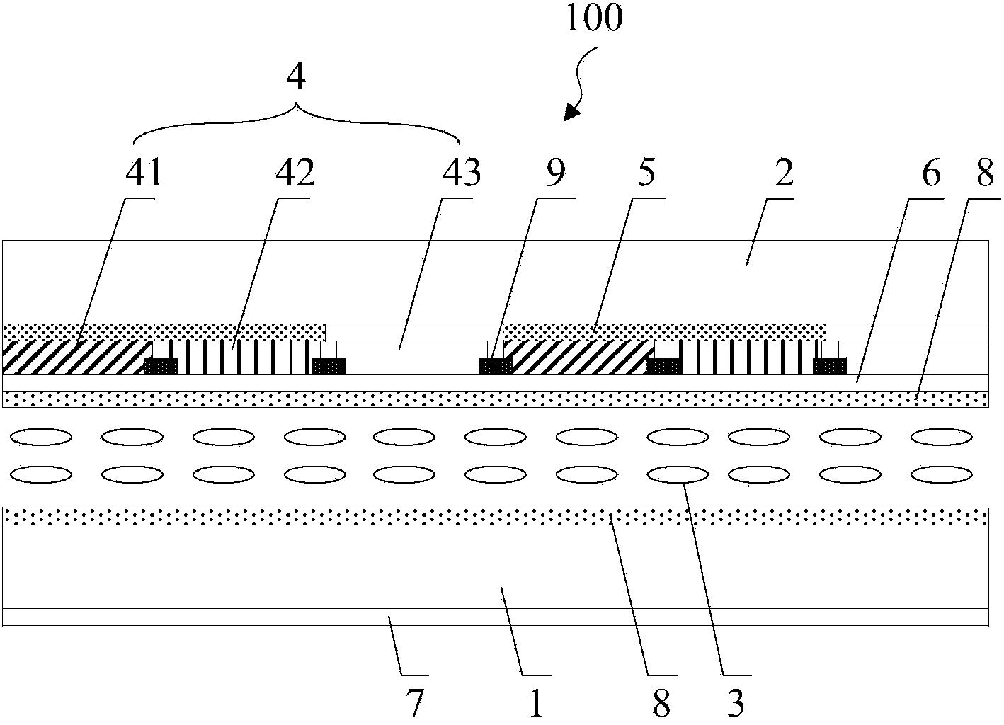
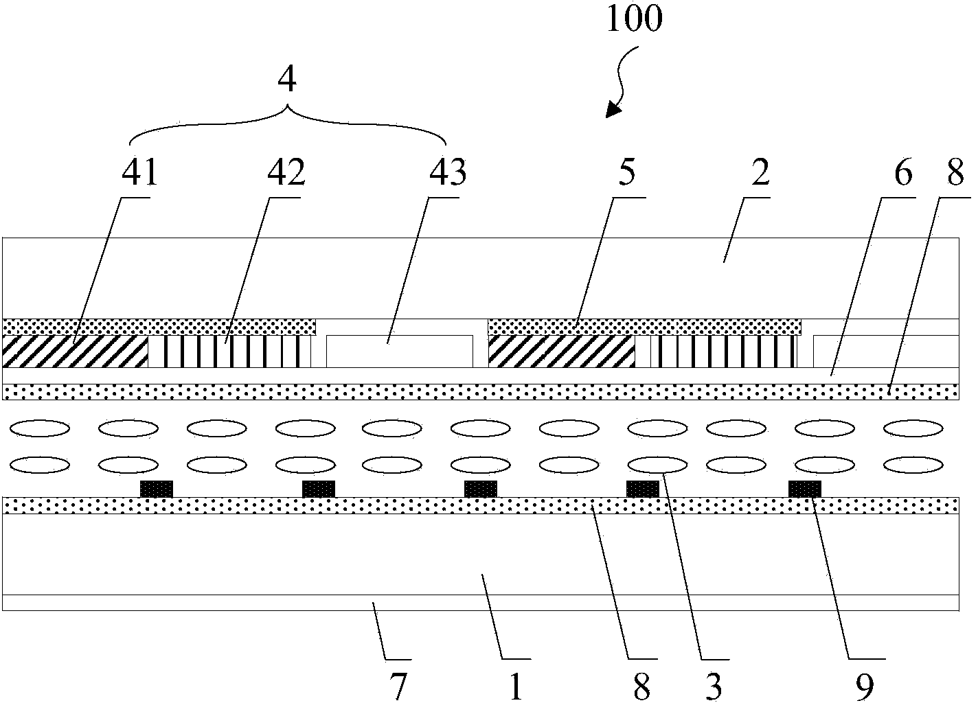
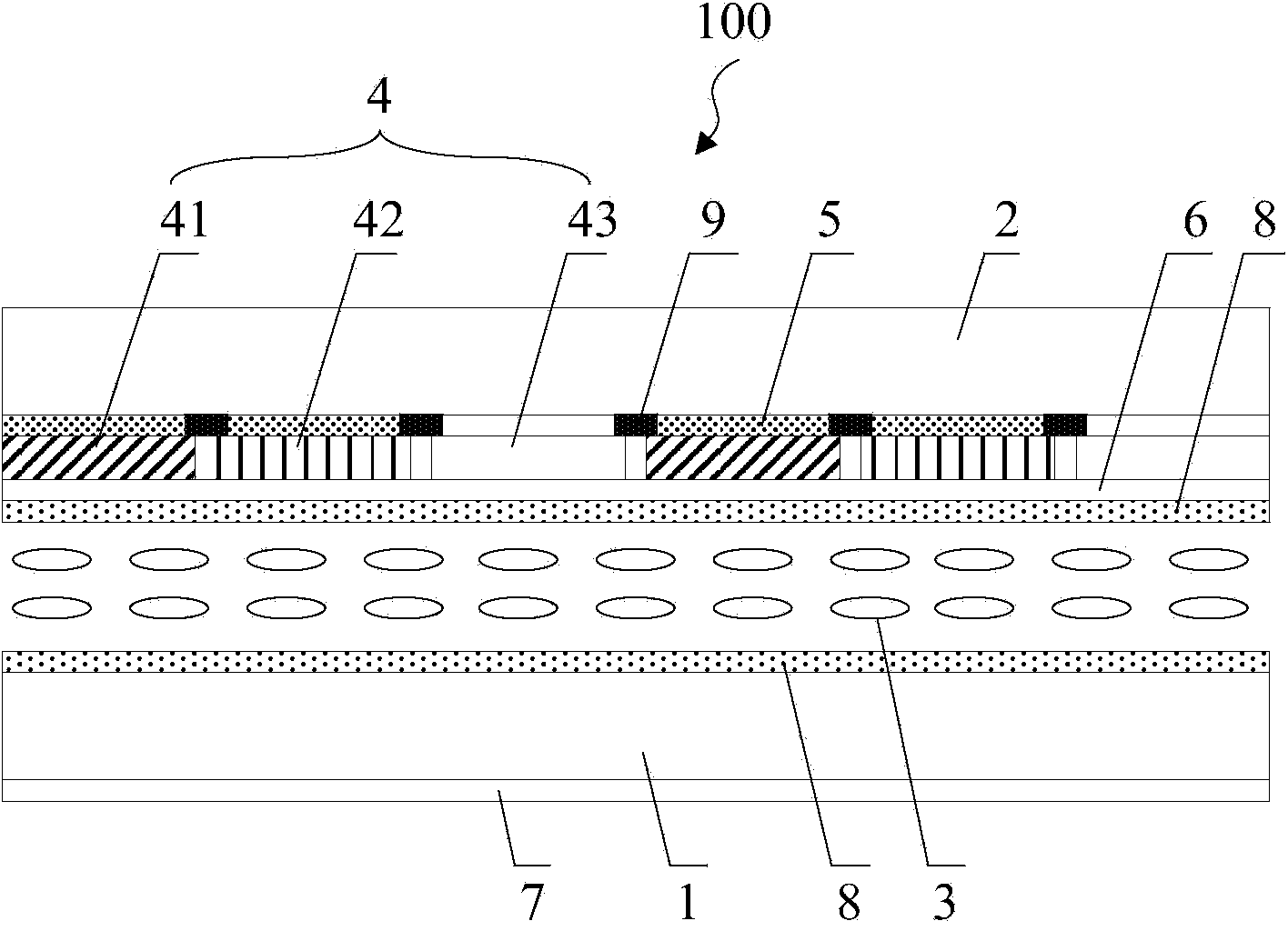
[0025] see figure 1 An embodiment of the present invention provides a display panel 100 , including an array substrate 1 and a color filter substrate 2 disposed opposite to each other, and a liquid crystal layer 3 disposed between the array substrate 1 and the color filter substrate 2 .

[0026] A quantum dot excitation layer 4 is arranged on the color mold substrate 2, an upper polarizing layer 6 is arranged between the color filter substrate 2 and the liquid crystal layer 3, a lowe...


PUM

PropertyMeasurementUnit
diameteraaaaaaaaaa
diameteraaaaaaaaaa
particle diameteraaaaaaaaaa

Abstract

The invention discloses a display panel and a display device, capable of improving light conversion efficiency of the display panel. The display panel comprises an array substrate and a color film substrate which are oppositely arranged as well as a liquid crystal layer between the array substrate and the color film substrate, wherein a quantum dot excitation layer is arranged on the color film substrate; an upper polarizing layer is arranged between the color film substrate and the liquid crystal layer; a lower polarizing layer is arranged on one surface, not adjacent to the liquid crystal layer, of the array substrate; and through the upper polarizing layer, linearly polarized light transmitted from the lower polarizing layer can reach the quantum dot excitation layer by keeping the state of the linearly polarized light.

Description

technical field [0001] The present invention relates to the field of display technology, in particular to a display panel and a display device. Background technique [0002] Quantum Dots (QD), also known as nanocrystals, are nanoparticles composed of II-VI or III-V elements. The particle size of quantum dots is generally between 1 and 20 nm. Since electrons and holes are quantum-confined, the continuous energy band structure becomes a discrete energy level structure with molecular characteristics, and can emit fluorescence after being excited. The emission spectrum of quantum dots can be controlled by changing the size of quantum dots. By changing the size and chemical composition of quantum dots, the emission spectrum can cover the entire visible light region. Taking cadmium telluride (CdTe) quantum dots as an example, when its particle size grows from 2.5nm to 4.0nm, their emission wavelength can be red-shifted from 510nm to 660nm. [0003] Quantum dots have high light c...

Claims


Application Information

Patent Timeline
Patent Type & Authority Applications(China)
IPC IPC(8): G02F1/1335
CPCG02F1/133512G02F1/133514G02F1/133533G02F1/133602G02F1/133617G02F1/133528G02F1/13362G02F2202/36G02F1/133565G02F1/133504G02F1/133615G02F1/133621G02F1/1337G02F2201/52G02F2203/055
Inventor 杨亚锋吕敬祝明
Owner BOE TECH GRP CO LTD
Learn More