
Liquid crystal safety card swiping equipment

A card swiping device and liquid crystal technology, which are applied in the directions of coin-operated devices for distributing discrete items, coin-operated devices for rental items, coin-free or similar appliances, etc., which can solve the problem of insufficient compact structure and low success rate. , occupying a large effective area, etc., to achieve the effect of not easy security attack, uniform force, and high success rate

Active Publication Date: 2015-02-04
FUJIAN NEWLAND PAYMENT TECH
View PDF8 Cites 5 Cited by
  • Summary
  • Abstract
  • Description
  • Claims
  • Application Information

AI Technical Summary

Problems solved by technology

But there are following defects in the existing simple IC card seat structure: on the one hand, the structure is still not compact enough, and the effective area is too large; on the other hand, if Figure 4 As shown, its contacts are exposed on the outer peripheral side, and the device is vulnerable to security attacks
[0005] The shape of the shrapnel of the existing magnetic head fails to fully consider the deformation of the process of swiping the magnetic stripe card, which affects the feel and success rate of swiping the magnetic stripe card. At the same time, the elastic fixing method mainly adopts screw fixing and hot-melt pillars
Among them, the use of screws is easy to cause deformation of the shrapnel after being fastened, resulting in defects such as poor consistency and low success rate of swiping the magnetic stripe card; using hot-melt pillars, the frequency and consistency of swiping the magnetic stripe card are not good

Method used


Image

  • Liquid crystal safety card swiping equipment
  • Liquid crystal safety card swiping equipment
  • Liquid crystal safety card swiping equipment

Examples


Embodiment Construction

[0030] The present invention will be described in further detail below in conjunction with the accompanying drawings and specific embodiments.

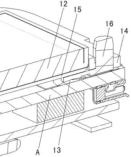
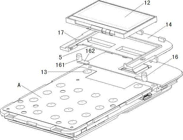
[0031] Such as Figure 1~2 As shown, a liquid crystal safe card swiping device includes a PCB board A, a card swiping device and a liquid crystal 12, the liquid crystal 12 is installed on the PCB board A through a liquid crystal bracket 14, a switch 13 is arranged between the PCB board and the liquid crystal, The liquid crystal support 14 extends a sheet 15 below the liquid crystal 12, and the liquid crystal support 14 is equipped with an elastic member 16 that presses down the switch 13 to switch on, and the elastic member 16 lifts the sheet 15 upwards at the same time to make the sheet The highest point of the upward deformation of 15 is close to the edge of the liquid crystal 12 .

[0032] In this embodiment, the switch 13 is a metal dome tact switch made on the PCB, but it is not limited thereto; of course, it can also be a micro...


PUM


Abstract

The invention relates to liquid crystal safety card swiping equipment, which comprises a PCB (printed circuit board), a card swiping device and liquid crystals, wherein a pot sheet which is positioned under the liquid crystals and covers a switch is arranged on the PCB, the liquid crystals are arranged on the PCB through a liquid crystal support frame, a thin sheet extends out from the liquid crystal support frame in a position under the liquid crystals, an elastic element downwards pressing the pot sheet is arranged on the liquid crystal support frame, and the elastic element simultaneously and upwards props up the thin sheet so that the highest point of the thin sheet after the upward deformation approaches to the edges of the liquid crystals. The maximum stress points of the liquid crystals are positioned on the edges, and meanwhile, small parts are averagely dispersed to the middle, so black spots due to liquid crystal deformation cannot be caused, and the appearance scheme exertion is ensured. When the liquid crystals receive safety attack, the safety triggering can be caused once the liquid crystals are turned up even when an external lens is turned open, and higher safety and high reliability are realized.

Description

technical field [0001] The invention relates to a liquid crystal safe card swiping device. Background technique [0002] At present, the safety structure of the LCD screen is often built in the lens, or the window area of ​​the display is made small, so that the LCD screen cannot be easily turned up; when the switch is directly installed under the LCD, the liquid crystal directly presses the switch. , so the back of the liquid crystal will also be pressed to produce black spots, which seriously affects the appearance. [0003] There are mainly two types of card holders currently in use: one is the integral type, which includes a card slot; the other is a simple type, and the card slot needs to be additionally structured. The main defect of the integral deck is that it occupies too much space on the circuit board. For handheld devices such as MPOS, mini payment, and IC card readers, it is required to be increasingly miniaturized. The space occupied seriously affects the stac...

Claims


Application Information

Patent Timeline
Patent Type & Authority Applications(China)
IPC IPC(8): G07F15/06
Inventor 叶滋杰高锵林林黄建新
Owner FUJIAN NEWLAND PAYMENT TECH
Learn More