Slide rail socket

A technology of slide rails and sockets, which is applied in the direction of electrical components, coupling devices, circuits, etc., can solve the problems of low flexibility of use and inability to realize effectively, so as to improve the safety of use, realize the cost of electricity, and avoid poor power contact Effect

Active Publication Date: 2015-02-04
临沂新科置业有限公司
View PDF3 Cites 20 Cited by
  • Summary
  • Abstract
  • Description
  • Claims
  • Application Information

AI Technical Summary

Problems solved by technology

[0004] The present invention provides a structure to solve the current situation that existing sockets have low flexibility in use and cannot effectively realize independent control of power supply transfer power supply or power-off state control for multiple sockets on the same socket board or on the same track. Reasonable, multiple sockets on the same track can be individually controlled to control the conduction of each socket to turn on or off the power supply, and use the slide rail socket with more flexible and convenient operation control

Method used


Image

  • Slide rail socket
  • Slide rail socket
  • Slide rail socket

Examples


Embodiment 1

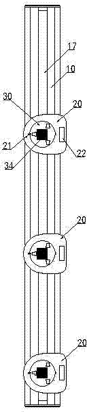
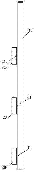
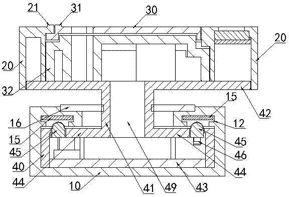
[0033] figure 1 , figure 2 , image 3 , Figure 4 , Figure 5 , Figure 8 , Figure 9 In the shown embodiment, a slide rail socket includes a slide rail base 10, a chute is opened in the slide rail base 10, and the two side walls 18 of the chute have a hook body 11 at the upper end of the slide rail base that extends upward and inwardly. , two conductive strips 14 are respectively installed at the back positions of the hook bodies 11 at the upper ends of the two slide rail bases along the length direction of the slide rail base 10, the conductive strips 14 are sheet-like long copper strips, and the two conductive strips 14 They are respectively electrically connected to the AC power supply, and the distance between the upper end hook bodies 11 of the two slide rail bases forms the upper port sliding track 17 in the length direction of the slide rail; Rotatable socket base, the specific number can be set separately according to the actual needs to form slide rail socket...

Embodiment 2

[0035] figure 1 , Image 6 , Figure 7 In the shown embodiment, the power socket includes a socket housing 20 and a socket body 36. A socket cover 30 is installed on the upper surface of the socket body 36. The socket housing 20 can be installed on the socket body 36 and the socket cover around the angle of rotation of the socket cover 30. At the outer periphery of the plate 30, the socket housing 20 and the socket cover 30 are respectively provided with reference lines aligned with each other, wherein the socket housing 20 is provided with a socket housing reference line 21, and the socket cover 30 is provided with a socket cover reference line 31 (See Image 6 , Figure 7 ); when rotated to align with the reference line, the cover plate jack 33 on the socket cover 30 is aligned with the socket jack on the socket body 36 and the plug can be inserted to connect electricity (see Image 6 ), after rotating and staggering the reference line, the cover hole on the socket cove...

Embodiment 3

[0037] A liquid crystal display window 22 is installed on the socket shell 20 , and a useful electricity metering circuit module is installed inside the socket shell 20 , and the electricity metering circuit module is electrically connected to the liquid crystal display window 22 . Others are identical with embodiment 1 or embodiment 2. It is more clear about the power consumption of each power socket, and it is easier to calculate the electricity cost of the power used by a single power socket.


PUM


Abstract

The invention discloses a slide rail socket. A slide rail base is internally provided with slide rail base upper hooks which upwards curve along two side walls of a chute. Two conductive elongated strips which are connected with AC electric power are respectively arranged at the back part of the upper hook of the slide rail base. The chute is internally provided with a plurality of rotatable socket bases. The upper end of each rotatable socket base is provided with a power socket which is exposed from the slide rail base. Connecting columns are connected between the rotatable socket base and the power socket. Each rotatable socket base is provided with two elastic conductive contact sheets which extend out of the upper end surface of the rotatable socket base. When the rotatable socket base rotates to a position where two conductive contact heads are respectively aligned with the two conductive elongated strips, the two conductive contact heads elastically extend upwards and electrically contact with the conductive elongated strips for conduction, and electric power is supplied to the power socket for supplying power. When the rotatable socket base rotates to a position where the two conductive contact heads are totally separated from the conductive elongated strips, the electric power to the power socket is switched off. A plurality of sockets on a same slide rail base can be singly controlled for switching on or switching off the electric power.

Description

technical field [0001] The invention relates to a socket, in particular to a socket in which multiple sockets are slidably installed on the same slide rail or track base. Background technique [0002] The socket, as a tool for realizing power transfer and power supply, is closely related to people's life and work. However, the existing sockets are either designed to install multiple power jacks on the same socket board, or to install multiple socket boards together to meet the needs of multiple power supply transfers. There are defects that the power transfer power supply is not flexible and convenient, the plugs are densely installed, and it is inconvenient to plug in and out. electric control. There are also slide rails used to install multiple sockets on one slide rail. However, you also have multiple sockets on the rail that are simultaneously controlled by the main switch to be in the conductive power supply or power-off state. The flexibility of use is low and cannot...

Claims


Application Information

Patent Timeline
Patent Type & Authority Applications(China)
IPC IPC(8): H01R25/14H01R13/71H01R13/447H01R13/66
CPCH01R13/447H01R13/665H01R13/6683H01R13/71H01R25/142H01R25/145
Inventor 张英吴王斌
Owner 临沂新科置业有限公司
Why Eureka
Try Eureka