

Multi-stage transmission
一种变速器、离合器的技术,应用在车辆变速箱、多传动比传动装置、传动装置等方向,能够解决变速器构件结构耗费等问题,达到实现行驶舒适性、改善消耗降低、减少结构空间的效果
- Summary
- Abstract
- Description
- Claims
- Application Information
AI Technical Summary
Problems solved by technology
Method used
Image

Examples
Embodiment Construction
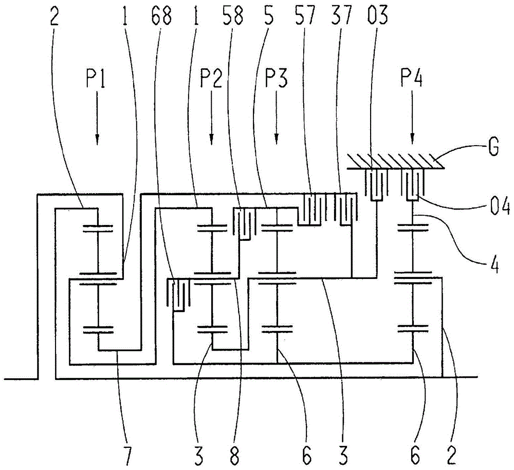
[0026] exist figure 1 shows a multi-stage transmission according to the invention, which comprises a drive shaft 1 , a driven shaft 2 and four planetary gearsets P1 , P2 , P3 and P4 which are arranged in a housing G. Planetary gear sets P1, P2, P3, P4 are in figure 1The example shown is configured as a negative planetary gear set. According to the invention, at least one of the planetary gear sets P1, P2, P3, P4 can be configured as a positive ratio planetary gear set, if the planet carrier connection and the ring gear connection are replaced at the same time and the value of the gear train transmission ratio is fixed If it is increased by 1 compared with the embodiment as a planetary gear set with a negative gear ratio.
[0027] In the illustrated embodiment, each planetary gear set P1, P2, P3, P4 is viewed axially as a first planetary gear set P1, a second planetary gear set P2, a third planetary gear set P3, a fourth planetary gear set P4 order settings. According to th...
PUM
 Abstract
Description
Claims
Application Information