Stirring device with cleaning structure

A technology of stirring device and stirring shaft, which is applied to mixers, dissolvers, mixers and other directions with rotating stirring devices, can solve the problems of cleaning, inconvenient use, no cleaning structure, and inability to slide up and down.

Inactive Publication Date: 2015-02-11
常州西夏墅工具产业创业服务中心
View PDF0 Cites 15 Cited by
  • Summary
  • Abstract
  • Description
  • Claims
  • Application Information

AI Technical Summary

Problems solved by technology

[0002] In the chemical production process, it is necessary to use a stirring device to stir the raw materials so that the raw materials are fully mixed and reacted. The existing stirring device includes a stirring shaft installed in the stirring tank and a stirring blade fixed on the stirring shaft. The stirring shaft Driven by the motor to rotate, the stirring shaft drives the stirring blades to rotate under the action of the motor to achieve the effect of stirring; the stirring device with such a structure

Method used


Image

  • Stirring device with cleaning structure
  • Stirring device with cleaning structure

Examples


Embodiment Construction

[0012] The present invention will be further described below with reference to the accompanying drawings and specific embodiments.

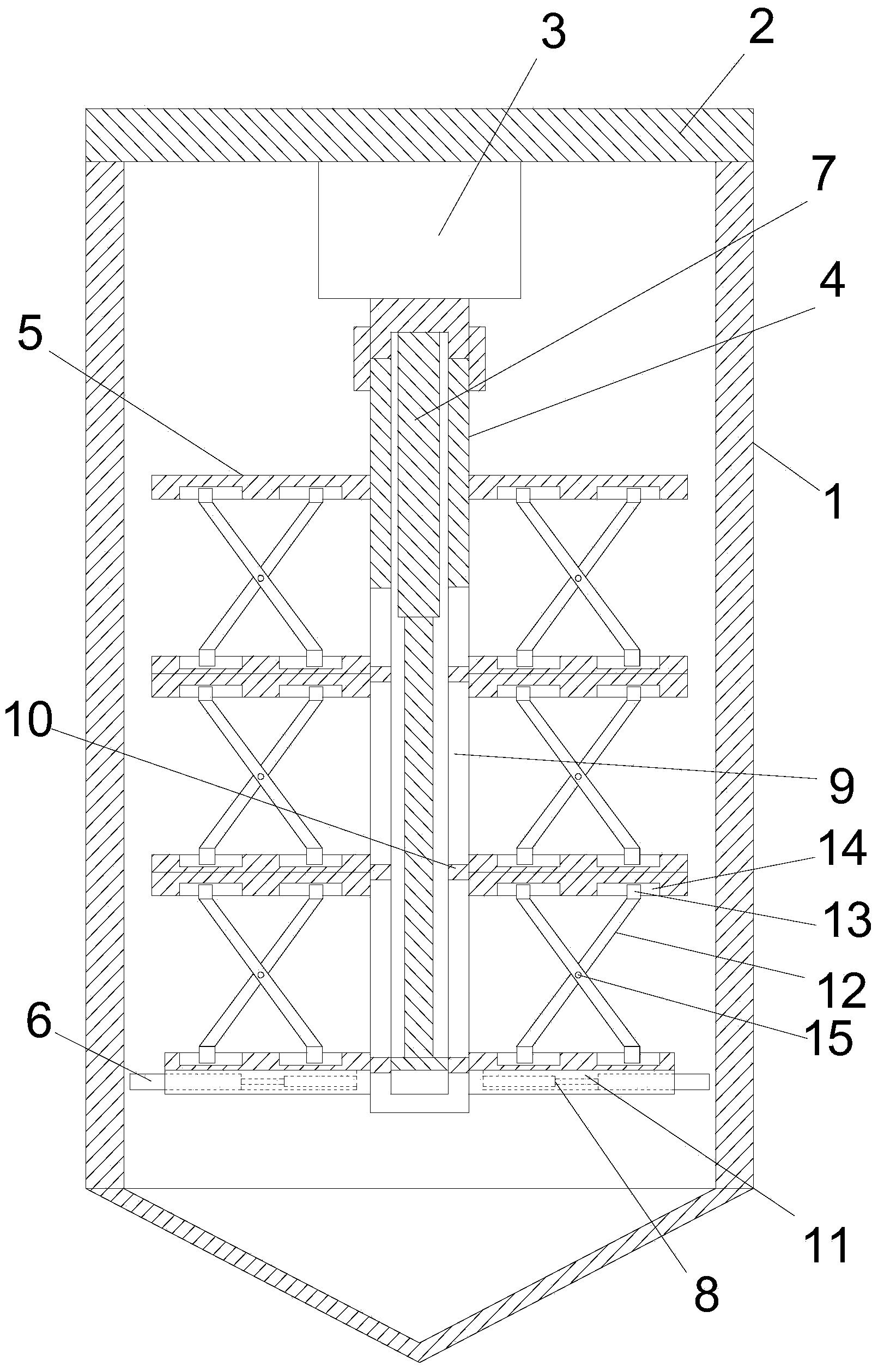
[0013] see figure 1 , 2 , a stirring device with a cleaning structure, including a tank body 1, an upper cover 2 covered on the tank body for capping the tank body, and a stirring structure arranged in the tank body, the stirring structure includes a fixed arrangement on the upper cover. The motor 3 and the stirring shaft 4 fixedly connected with the motor shaft are sleeved with multi-layer stirring blades 5 arranged up and down in sequence, and the upper and lower adjacent stirring blades are connected by a movable connection mechanism. The uppermost stirring blade In order to be fixed on the stirring shaft, it can be fixed by means of bolts, screws or welding. The stirring blades below the uppermost layer can slide up and down along the stirring shaft. In the tank, there is a fixed connection with the lowermost stirring blade and can be stretc...


PUM


Abstract

The invention relates to a stirring device with a cleaning structure. The stirring device comprises a tank body, an upper cover and a stirring structure arranged in the tank body, wherein the stirring structure comprises a motor fixed on the upper cover, a stirring shaft fixedly connected with a motor shaft and a plurality of layers of stirring blades which sleeve the stirring shaft and are sequentially arranged vertically; the upper and lower adjacent stirring blades are connected by a movable connecting mechanism; the stirring blades at the uppermost layer are fixed on the stirring shaft; the stirring blades below the uppermost layer can slide vertically along the stirring shaft; the tank body is internally provided with a vertical telescopic mechanism which is fixedly connected with the bottommost layer of stirring blades and can stretch vertically; the stirring blades at the bottommost layer are provided with a telescopic sheet which can be telescopic left and right and is in contact with the inner wall of the tank body and a horizontal telescopic mechanism for driving the telescopic sheet to stretch. According to the invention, the positions of the stirring blades can be adjusted according to the depth of raw materials in the tank body, and the stirring efficiency and effect are improved, the inner wall of the tank body can be cleaned automatically, the labor intensity of workers can be lowered, and the stirring device is convenient to use.

Description

technical field [0001] The invention relates to the technical field of stirring equipment, in particular to a stirring device with a cleaning structure. Background technique [0002] In the process of chemical production, it is necessary to use a stirring device to stir the raw materials, so that the raw materials are fully mixed and reacted. The existing stirring device includes a stirring shaft arranged in the stirring tank and a stirring blade fixed on the stirring shaft. Driven by the motor to rotate, under the action of the motor, the stirring shaft drives the stirring blade to rotate to realize the stirring effect; the stirring device with this structure has the following defects: 1. The stirring blade is fixed on the stirring shaft and cannot slide up and down, so it cannot The position of the stirring blade is adjusted according to the depth of the raw materials in the tank, resulting in poor stirring effect; 2. After a period of use, the raw materials form accumulat...

Claims


Application Information

Patent Timeline
IPC IPC(8): B01F7/18
Inventor 邹春英袁征孙祥龙
Owner 常州西夏墅工具产业创业服务中心
Why Eureka
Try Eureka