Tool changer assembly

A technology for tool magazines and components, which is applied in the direction of metal processing machinery parts, clamping, support, etc., can solve the problems of complex overall structure, inconvenient manufacturing, and high cost of tool magazine components, and achieve compact structure, low cost, and small volume Effect

Inactive Publication Date: 2015-02-11
SHANGHAI ZHENZHENG NUMERICAL CONTROL MACHINE TOOL CO LTD
View PDF7 Cites 0 Cited by
  • Summary
  • Abstract
  • Description
  • Claims
  • Application Information

AI Technical Summary

Problems solved by technology

[0002] The overall structure of the existing tool magazine assembly is r

Method used


Image

  • Tool changer assembly
  • Tool changer assembly
  • Tool changer assembly

Examples


Embodiment Construction

[0026] In order to make the technical means, creative features, goals and effects achieved by the present invention easy to understand, the present invention will be further described below in conjunction with specific illustrations.

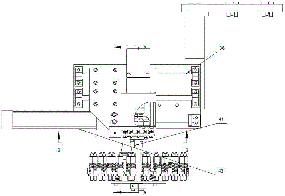
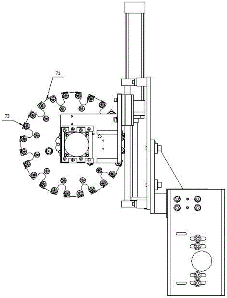
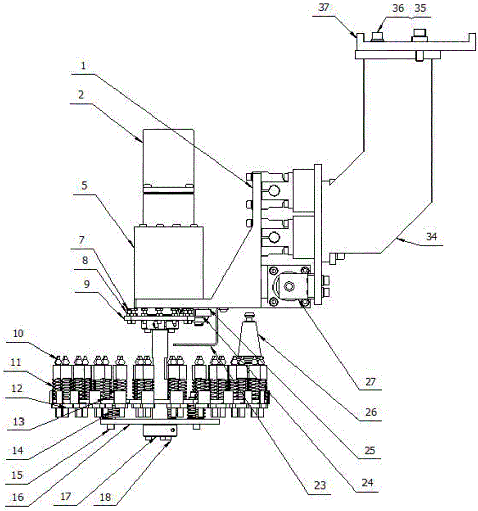
[0027] Such as Figure 1-5 As shown, the tool magazine assembly has: a tool magazine fixing bracket I34, which is equipped with a tool magazine fixing bracket II37 through a washer 35 and an inner hexagon socket head screw 36; a tool magazine fixing plate 48 installed on the tool holder fixing bracket; The linear guide rail 38 on the tool magazine fixed plate; the tool magazine fixed plate I1 installed on the linear guide rail through a slider, and a cylinder assembly that drives the tool magazine fixed plate I to move is arranged between the tool magazine fixed plate and the tool magazine fixed plate I 42; the back-to-back angular contact ball bearing 45 is rotatably installed on the rotating shaft 41 of the tool magazine fixed plate 1 by coope...


PUM


Abstract

The invention discloses a tool changer assembly. The tool changer assembly comprises a tool changer fixing bracket I, a tool changer fixing plate, a linear guide rail, a tool changer fixing plate I, a rotary shaft, a cutter assembly and a positioning disk, wherein the tool changer fixing plate is mounted on the tool changer fixing bracket; the linear guide rail is mounted on the tool changer fixing plate; the tool changer fixing plate I is mounted on the linear guide rail through a sliding block; an air cylinder assembly, which drives the tool changer fixing plate I to move, is arranged between the tool changer fixing plate and the tool changer fixing plate I; the rotary shaft is rotationally mounted on the tool changer fixing plate I, and the upper part of the rotary shaft is connected to an alternating current motor through a coupler; the cutter assembly is mounted at the lower part of the rotary shaft and is used for assembling a tool; the positioning disk is mounted below the tool changer fixing plate I and is positioned on the rotary shaft; a positioning mechanism matched with the positioning disk is arranged below the fixing plate I; a signal fixing bracket is mounted below the tool changer fixing plate I and is provided with an approach switch which is matched with the positioning disk and is connected to a control system. The tool changer assembly has the benefits of compact overall structure, small size, low cost and convenience in manufacturing.

Description

technical field [0001] The invention relates to a tool magazine assembly. Background technique [0002] The overall structure of the existing tool magazine assembly is relatively complicated, the cost is high, and the manufacture is inconvenient. Contents of the invention [0003] The object of the present invention is to provide a tool magazine assembly to solve the above problems. [0004] In order to achieve the above object, the present invention adopts the following technical solutions: [0005] Tool magazine assembly, which has: [0006] Tool magazine fixing bracket I (34); [0007] The tool magazine fixing plate (48) that is installed in the tool rest fixing bracket; [0008] The linear guide rail (38) that is installed on the tool magazine fixed plate; [0009] Installed on the tool magazine fixed plate I (1) of the linear guide rail by a slide block, a cylinder assembly (42) that drives the tool magazine fixed plate I to move is provided between the described...

Claims


Application Information

Patent Timeline
IPC IPC(8): B23Q3/155
CPCB23Q3/155
Inventor 余国梁
Owner SHANGHAI ZHENZHENG NUMERICAL CONTROL MACHINE TOOL CO LTD
Why Eureka
Try Eureka