Automatic transmission dog clutch control unit

A claw clutch, automatic transmission technology, applied in the direction of mechanical drive clutch, clutch, transmission control, etc., can solve the problems of longer shifting time, time-consuming, longer time, etc.

Inactive Publication Date: 2015-02-11
AISIN SEIKI KK
View PDF7 Cites 4 Cited by
  • Summary
  • Abstract
  • Description
  • Claims
  • Application Information

AI Technical Summary

Problems solved by technology

As a result, when it is judged that the sleeve cannot be engaged with the dog clutch of the idler gear, the jaws are already pressed against the sleeve, and the mutual rotation speed difference between the sleeve and the idler gear becomes smaller...

Method used


Image

  • Automatic transmission dog clutch control unit
  • Automatic transmission dog clutch control unit
  • Automatic transmission dog clutch control unit

Examples


Embodiment Construction

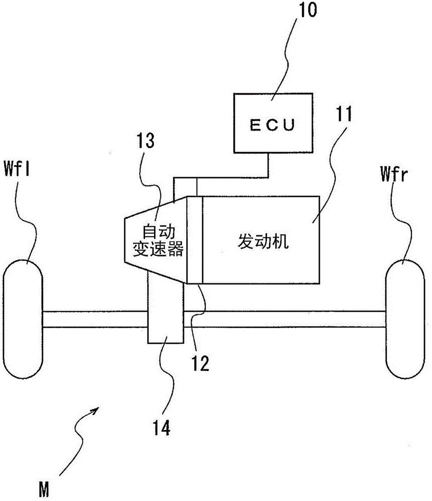
[0099] Next, an embodiment in which an automatic transmission provided with the dog clutch control device for an automatic transmission of the present invention is applied to a vehicle will be described with reference to the drawings. figure 1 It is a schematic diagram showing the structure of the vehicle. Such as figure 1 As shown, the vehicle M includes an engine 11, a clutch 12, an automatic transmission 13, a differential device 14, and drive wheels (left and right front wheels) Wfl, Wfr. The engine 11 generates driving power by burning fuel. The driving force of the engine 11 is transmitted to drive wheels Wfl, Wfr via a clutch 12, an automatic transmission 13, and a differential device 14 (so-called FF vehicle).

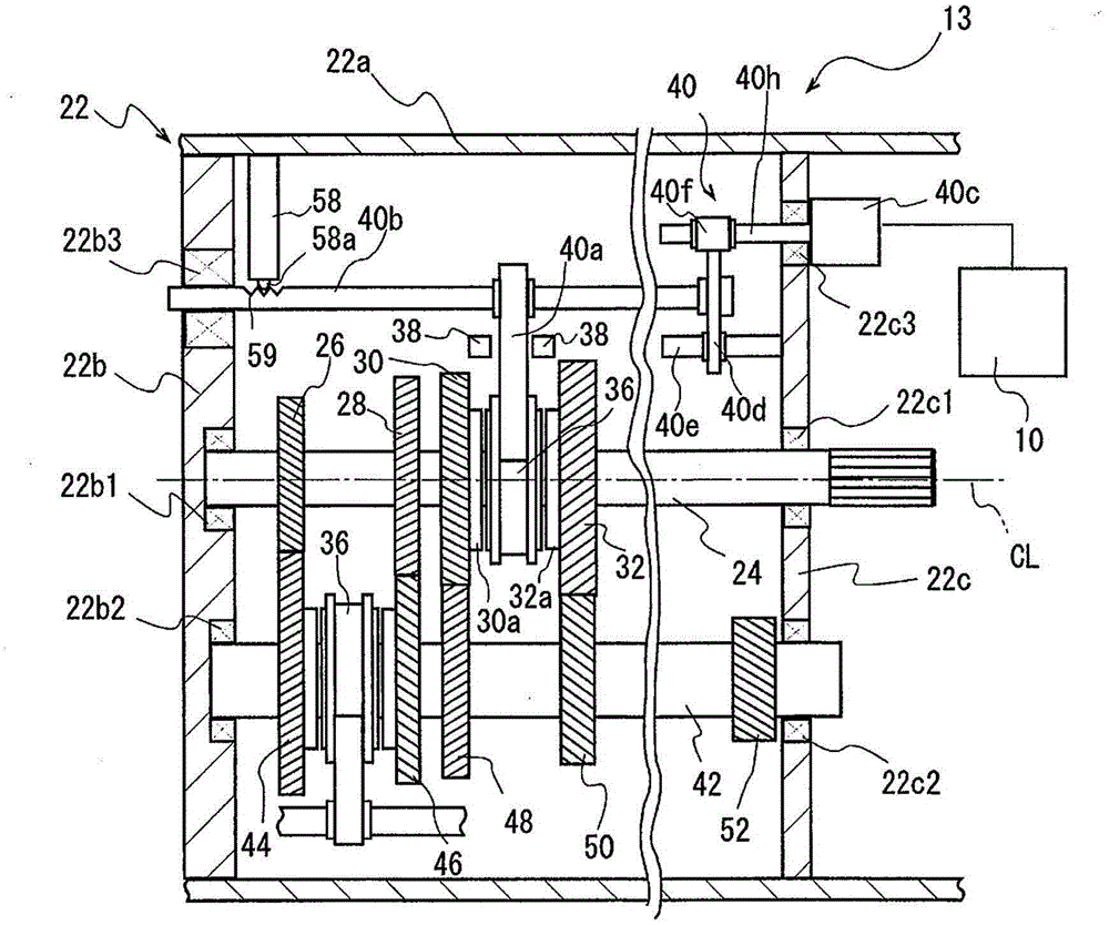
[0100] The clutch 12 is automatically disengaged or engaged according to an instruction from a control unit (ECU) 10 . The automatic transmission 13 incorporates a dog clutch transmission mechanism, and automatically selects, for example, 6 forward speeds and ...


PUM


Abstract

A dog clutch control unit for an automatic transmission (13) includes: a dog clutch transmission mechanism including: a rotating shaft; a clutch ring (30, 32, 44, 46); a clutch hub (34); a sleeve (36) fitted to the clutch hub by means of a spline; an axially moving unit (40); a dog clutch portion (30a); and a stroke position sensor (38), the spline having high teeth higher than remaining low teeth, and the dog clutch portion including the same number of clutch front teeth as the high teeth, and the dog clutch portion including clutch rear teeth; and a control unit (10) configured to control an action of the axially moving unit on the basis of a detected position detected by the stroke position sensor.

Description

technical field [0001] The present invention relates to a control device for dog clutches used in automatic transmissions for vehicles. Background technique [0002] Conventionally, a powertrain of a vehicle has a transmission that converts torque and rotational speed in order to transmit rotation and torque from a driving device such as an engine or an electric motor used for driving to driving wheels according to driving conditions. There are several types of transmissions, but known, for example, are the following constant mesh transmissions, that is, a plurality of idler gears that are fitted so as to be rotatable with respect to a rotation shaft connected to a drive wheel and cannot move in the direction of the rotation axis, and A plurality of gears arranged around an intermediate shaft whose rotation axes are arranged in parallel are always in mesh. In this transmission, a sleeve that is spline-fitted with the rotating shaft so as to be movable in the direction of th...

Claims


Application Information

Patent Timeline
IPC IPC(8): F16H61/02F16H63/30
CPCF16D21/04F16D11/04F16D2011/008F16D2011/002F16D11/10F16D48/06F16D48/064F16D2500/10412F16D2500/10462F16D2500/1085F16D2500/3026F16D2500/30408F16D2500/3166F16D2500/50239F16D2500/50607F16D2500/525
Inventor 三岛启介岩崎靖久甲村雅彦岩田崇司森匡辅
Owner AISIN SEIKI KK
Why Eureka
Try Eureka