A washing machine water inlet valve and water inlet method

A water inlet valve and washing machine technology, applied in the field of washing machines, can solve the problems of high power consumption, complicated structure setting, unfavorable practical promotion and application, etc.

Active Publication Date: 2017-02-01
SUZHOU SAMSUNG ELECTRONICS CO LTD +1
View PDF7 Cites 0 Cited by
  • Summary
  • Abstract
  • Description
  • Claims
  • Application Information

AI Technical Summary

Problems solved by technology

[0006] It can be seen from the above that the structure of the existing electromagnetic water inlet valve of the washing machine requires that the electromagnetic coil is always in the energized state when the water is in the state, and the power consumption is large, and because the electromagnetic coil is always in the long working state when the water is in the state , inevitably produces electromagnetic noise, and further shortens the service life of the water inlet valve of the washing machine
[0007] In order to solve the above technical problems, the Chinese patent with the publication number CN2210291Y discloses a solenoid valve, in which a pressing gear ring, a pressure gear ring, a supporting shaft sleeve and a check rod are added, and the moving iron core is placed on the The bottom of the catheter, the upper part is loaded with the pressure gear ring, the pressure gear ring, the support shaft sleeve and the spring, and the check rod is placed in the center hole of the support shaft sleeve, the pressure gear ring and the pressure gear ring, in order to achieve It does not consume electricity in the working state of the solenoid valve, but the gear ring matching structure adopted in this patent is too complicated to be applied in practice

Method used


Image

  • A washing machine water inlet valve and water inlet method
  • A washing machine water inlet valve and water inlet method
  • A washing machine water inlet valve and water inlet method

Examples


Embodiment Construction

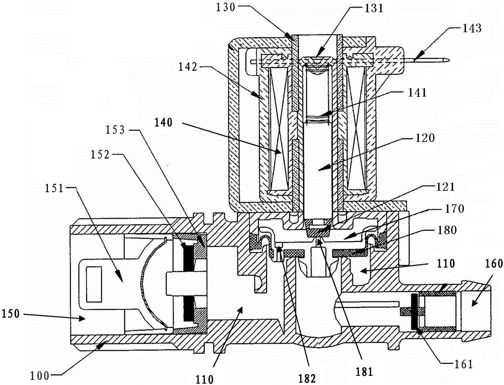
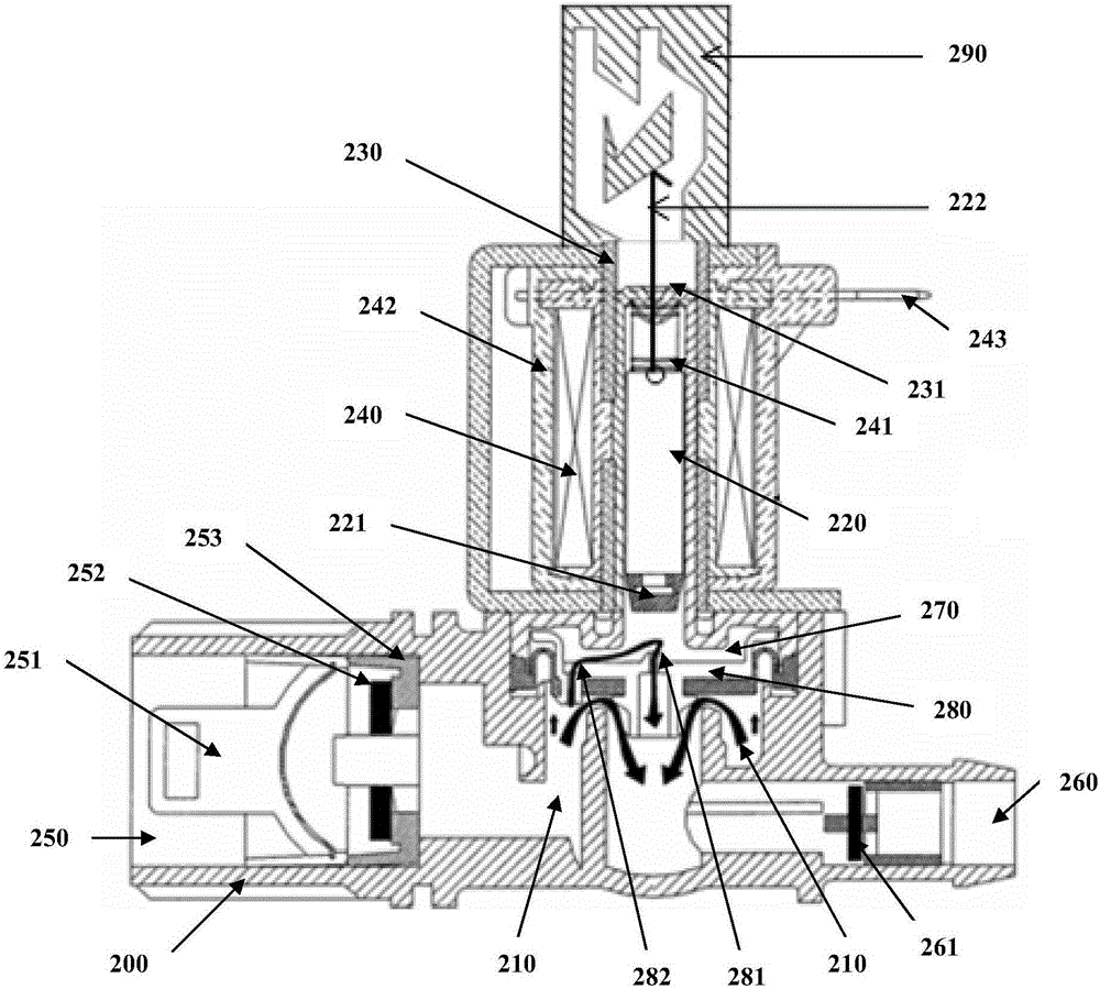
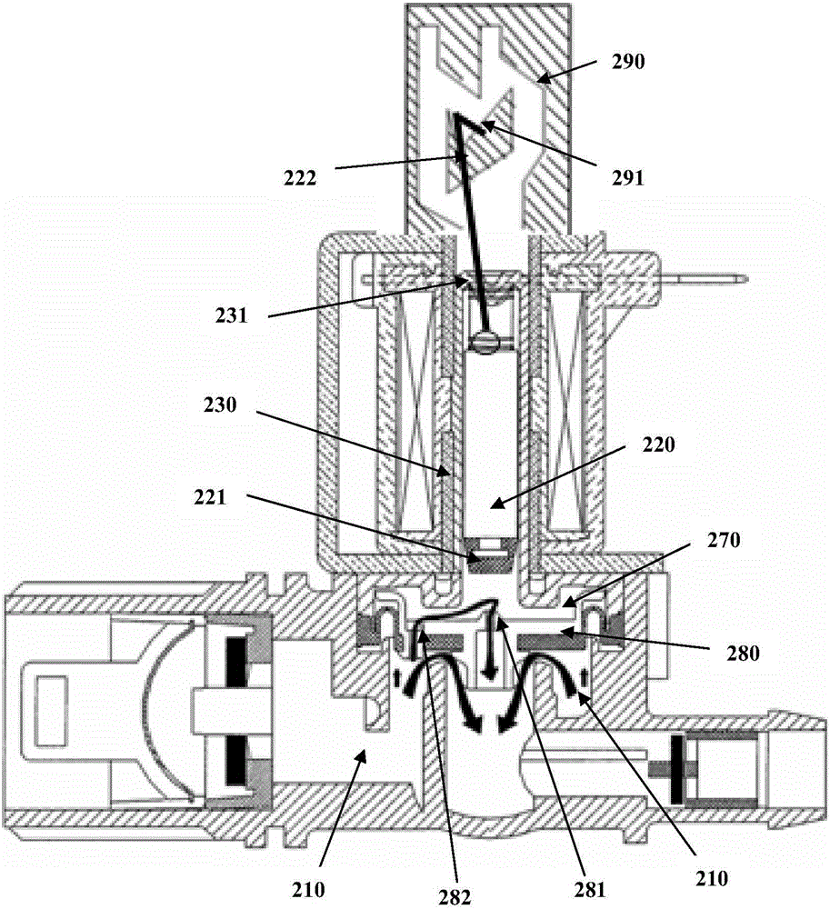
[0040] The embodiment of the invention discloses a water inlet valve for a washing machine, which includes a valve chamber, a sleeve, a valve core located on the inner circumference of the sleeve and movable up and down along the sleeve, an electromagnetic coil located on the outer circumference of the sleeve, and a water inlet located on the valve chamber. And the water outlet, the back pressure chamber under the sleeve and the diaphragm plate with a central hole, the upper end of the sleeve is provided with a guide groove, the guide groove is provided with a locking part, and the upper end of the valve core is fixed with a radial swing The hook, the electromagnetic coil adopts pulse-type electrification to generate pulse-type electromagnetic force on the valve core; among them,

[0041] The spool includes a first state, a second state and a third state;

[0042] The first state is: the lower end of the valve core is socketed and sealed with the central hole, and the hook is ...


PUM


Abstract

The invention discloses a washing machine water inlet valve and a water inlet method. The washing machine water inlet valve comprises a valve chamber, a casing, a valve core, an electromagnetic coil, a water inlet, a water outlet, a back pressure chamber and a membrane plate, wherein the valve core is positioned on the inner circumference of the casing and can move up and down along the casing; the electromagnetic coil is positioned at the periphery of the casing; the water inlet and the water outlet are formed in the valve chamber; the back pressure chamber is positioned below the casing; the membrane plate is provided with a central hole; the upper end part of the casing is provided with a guide groove; the guide groove is provided with a clamping part; the upper end part of the valve core is fixedly provided with a hook which can swing radially; the electromagnetic coil produces pulse type electromagnetic force to the valve core by using pulse type electrification. According to the washing machine water inlet valve and the water inlet method, the power consumption of the water inlet valve is reduced, the water inlet noise is reduced, and meanwhile the service life of the washing machine water inlet valve is prolonged on the premise of meeting the requirement of a water inlet function; the water inlet valve has a simple structure and contributes to large-scale popularization and application.

Description

technical field [0001] The invention belongs to the field of washing machines, and in particular relates to a washing machine water inlet valve and a water inlet method. Background technique [0002] The water inlet valve of the washing machine is a component used to control the flow and direction of the water inlet of the washing machine, and the electromagnetic water inlet valve is generally used in the existing market. see figure 1 The electromagnetic water inlet valve 100 shown in the prior art includes a valve chamber 110, a valve core 120 with a valve core cap 121 at the lower end, a sleeve 130, an electromagnetic coil 140 located at the inner circumference of the sleeve 130, and a The water inlet 150 and the water outlet 160 on the chamber 110 and the back pressure chamber 170 and the diaphragm plate 180 located below the casing 130, the diaphragm plate 180 is provided with a central hole 181 and side holes 182, and is located between the back pressure chamber 170 an...

Claims


Application Information

Patent Timeline
Patent Type & Authority Patents(China)
IPC IPC(8): F16K31/10
CPCD06F39/088F16K31/0672F16K31/0675F16K31/126
Inventor 周旭东
Owner SUZHOU SAMSUNG ELECTRONICS CO LTD
Why Eureka
Try Eureka