Anchoring connector of ductile cast iron pipe
An anchoring technology for ductile iron pipes, which is applied in the direction of pipes/pipe joints/fittings, sealing surface connections, passing components, etc., can solve the problems of poor anti-slipping ability and complicated installation of ductile iron pipe joints, etc., and achieve strong anti-slipping ability, The effect of simple structure and convenient installation
- Summary
- Abstract
- Description
- Claims
- Application Information
AI Technical Summary
Problems solved by technology
Method used
Image
Examples
Embodiment 1
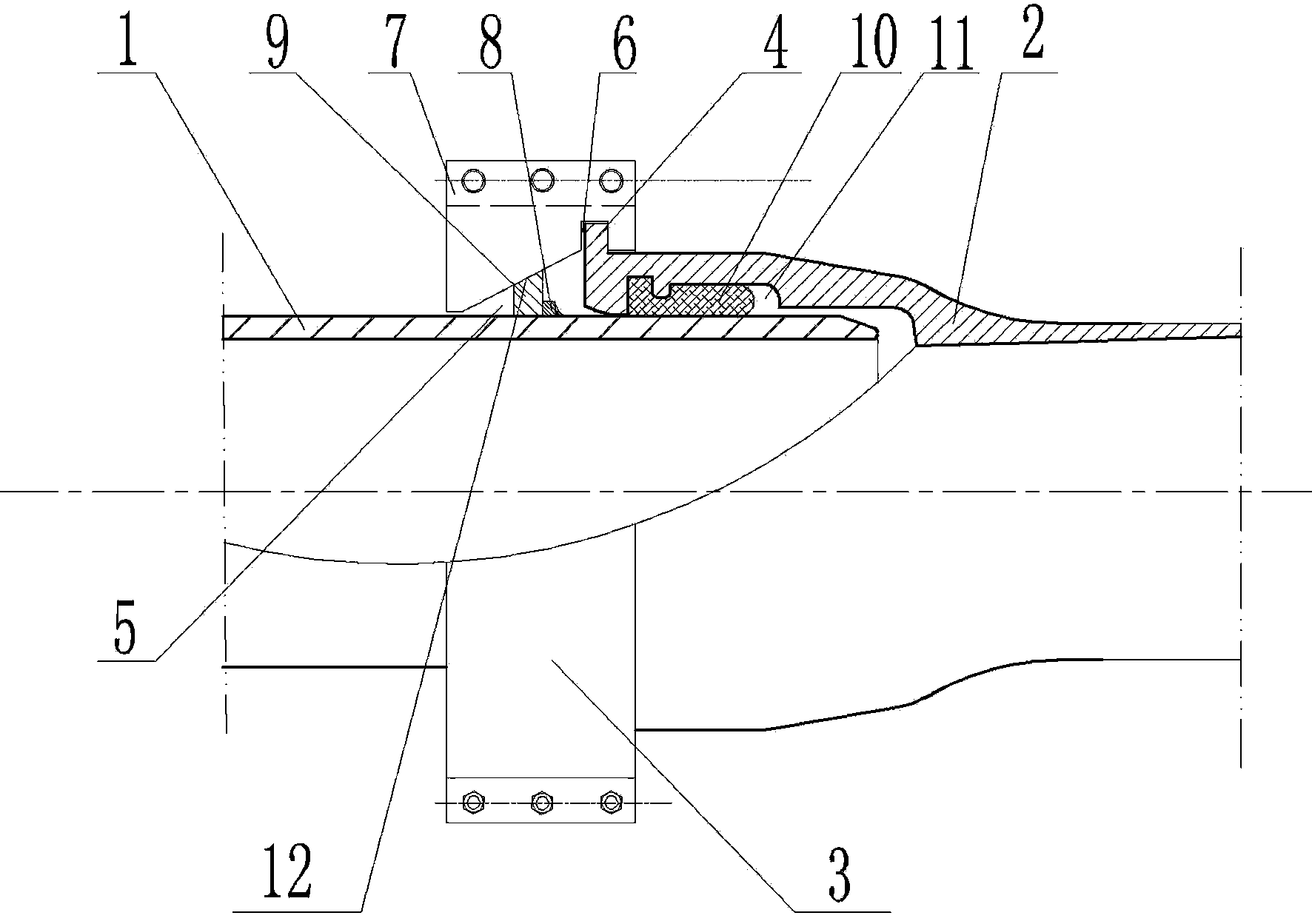
[0016] like figure 1 An embodiment of the ductile iron pipe anchoring interface of the present invention is shown. like figure 1 As shown, the ductile iron pipe anchoring interface of the present invention includes a socket 2, a socket 1 inserted in the socket 2 and an annular fixing ring 8 fixed on the outer surface, and the socket 2 and socket 1 are sleeved on the socket 1 to connect the socket 2 and the socket 1 together pressure flange 3. like figure 1 As shown, the inner surface of the socket 2 is provided with an annular sealing groove 11 embedded with a sealing ring 10, and an annular cylindrical protruding ring 4 is fixed on the outer surface. It should be noted here that the shape of the protruding ring 4 is optimal. Choose a cylindrical shape, and the cylindrical protrusion is more convenient for the casting process of the socket, but it is not limited to this shape, any shape that can prevent the axial pull-out force is acceptable, such as the shape of the hook h...
Embodiment 2
[0018] In order to increase the anti-off strength of the interface and achieve better anti-off effect. like figure 1 As shown, on the basis of the first embodiment, there is a stop ring 9 movably fitted on the socket 1 , and the stop ring 9 is located on the left side of the fixed ring 8 . like figure 1 As shown, the stop ring 9 is located in the tapered inner hole 5, that is to say, the stop ring 9 is located in the space formed by the tapered inner hole 5 and the fixed ring 8. This structure means that the diameter of the outer surface of the stop ring 9 is larger than that of the tapered The smallest diameter on the left side of the inner hole 5 is at the same time the inner surface diameter smaller than the outer surface diameter of the retaining ring 8 . In order to further increase the anti-strength of the interface, such as figure 1 As shown, the outer surface of the retaining ring 9 is set as the tapered surface 12 with the same slope angle as the tapered inner...
PUM
 Abstract
Description
Claims
Application Information
 - R&D
- Intellectual Property
- Life Sciences
- Materials
- Tech Scout
- Unparalleled Data Quality
- Higher Quality Content
- 60% Fewer Hallucinations
Browse by: Latest US Patents, China's latest patents, Technical Efficacy Thesaurus, Application Domain, Technology Topic, Popular Technical Reports.
© 2025 PatSnap. All rights reserved.Legal|Privacy policy|Modern Slavery Act Transparency Statement|Sitemap|About US| Contact US: help@patsnap.com

