Fire starters and fire starter sets

A technology for ignition parts and connecting parts, applied in the field of pyrotechnics manufacturing, can solve the problems of transportation of ignition parts, increase the safety hazard in the production process, and it is difficult to determine the length of bridge wires, etc., so as to improve uniformity, avoid accidental detonation, and improve ignition consistency. sexual effect

Active Publication Date: 2019-05-07
南通炜天电子科技有限公司
View PDF5 Cites 0 Cited by
  • Summary
  • Abstract
  • Description
  • Claims
  • Application Information

AI Technical Summary

Problems solved by technology

Since the diameter of the bridge wire is generally in the micron level, it is difficult to determine the length of the bridge wire by manual welding, so it is difficult to ensure the consistency of the resistance of the bridge wire, which will affect the consistency of the ignition performance of the igniter
At the same time, the efficiency of the above-mentioned manual welding process is low, which is not conducive to the mass production of ignition parts
[0003] When the ignition agent wraps the ignition bridge wire, because there is no restriction on the flow of the agent, the agent will flow unevenly under the action of gravity, which will affect the ignition performance of the detonator
[0004] In addition, after the ignition bridge wire is wrapped by the igniting agent, the igniting agent is exposed outside, which increases the safety hazard in the production process; moreover, it is easy to be damaged during the production process, resulting in the failure of the detonator to ignite normally
In addition, the fire starter with the ignition bridge wire in a bare state cannot be transported as a separate product, thus causing inconvenience to the production and use of the fire starter

Method used


Image

  • Fire starters and fire starter sets
  • Fire starters and fire starter sets
  • Fire starters and fire starter sets

Examples


Embodiment Construction

[0022] The technical solution of the present invention will be described in further detail below in conjunction with the accompanying drawings and specific embodiments.

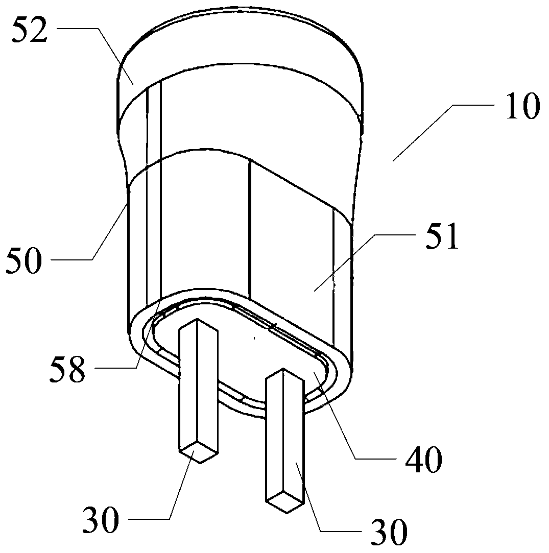
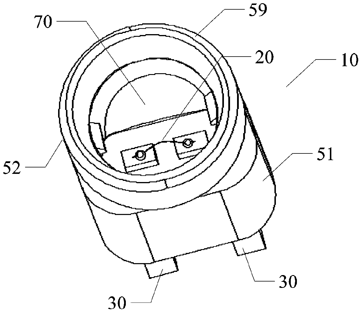
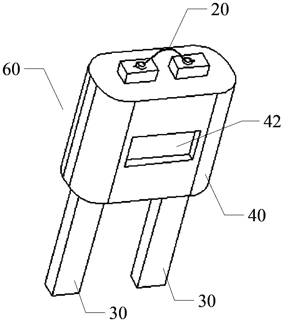
[0023] Fire starter 10 provided by the present invention, see figure 1 and figure 2 As shown, it is used to connect with the ignition control circuit board. In particular, the above-mentioned fire starter 10 includes an ignition bridge wire 20, a pair of bridge wire connectors 30, a base 40 and a cavity shell 50, the ignition bridge wire 20, a pair of bridge wires Connector 30, and base 40 jointly form an assembly 60, such as image 3 As shown; a pair of bridge wire connectors 30 are fixed by the base 40 and are insulated from each other; two ends of a pair of bridge wire connectors 30 extend out of the base 40, and one end is welded with an ignition bridge wire 20, so that a pair of bridge wire connectors 30 to form an electrical connection, and the other end is used to form an electrical connection with ...


PUM


Abstract

The invention discloses an ignition part. The ignition part is connected with an ignition control circuit board and comprises an ignition igniter wire, a pair of igniter wire connecting parts, a base and a cavity shell; an assembling part is jointly formed by the ignition igniter wire, the igniter wire connecting parts and the base; the igniter wire connecting parts are fixed through the base and are insulated from each other; the two ends of the igniter wire connecting parts extend out of the base; one end of each igniter wire connecting part is welded to the ignition igniter wire, and therefore the igniter wire connecting parts are electrically connected; the other ends of the igniter wire connecting parts are used for being electrically connected with the ignition control circuit board; the assembling part is assembled with a cavity shell, and therefore a first portion of the cavity shell is in interference fit with the base; the second portion of the cavity shell and the assembling part are welded to one end of the ignition igniter wire to form a cavity. According to the ignition part, ignition consistency of a detonator is easily improved; the cavity can play a role in protecting the ignition igniter wire, and the ignition part can be used as an independent product to be conveyed. The invention further provides an ignition part set; the mode of producing ignition parts by taking a set as a unit is adopted, and therefore the production efficiency of the ignition part is easily improved.

Description

technical field [0001] The invention relates to the technical field of pyrotechnics manufacture, in particular to a structure of a igniter for a detonator and a igniter group. Background technique [0002] As the ignition element of the detonator, the ignition part directly affects the firing consistency of the detonator. Whether the detonator can have a high ignition consistency has a lot to do with the quality of the igniter. In the existing production process of the ignition part of the electric detonator, the bridge wire is often directly welded to the end face of the leg of the detonator, and this process is usually carried out manually. Since the diameter of the bridge wire is generally on the order of microns, it is difficult to determine the length of the bridge wire by manual welding, so it is difficult to ensure the consistency of the resistance of the bridge wire, which will affect the consistency of the ignition performance of the igniter. At the same time, the...

Claims


Application Information

Patent Timeline
Patent Type & Authority Patents(China)
IPC IPC(8): F42C19/12
Inventor 颜景龙张文佳
Owner 南通炜天电子科技有限公司
Why Eureka
Try Eureka