Supercharge Your Innovation With Domain-Expert AI Agents!

System and method for realizing display control of dynamic icons on OSD (on screen display) interface in electronic equipment

A technology of electronic equipment and dynamic icons, which is applied in the field of electronic screen display and electronic equipment display dynamic icons, can solve the problems of large files, large dynamic icon data, and few audio and video works, etc., to achieve simple system structure, reduce memory usage, Realize the effect of seamless switching

Active Publication Date: 2015-02-11
CRM ICBG (WUXI) CO LTD
View PDF4 Cites 7 Cited by
  • Summary
  • Abstract
  • Description
  • Claims
  • Application Information

AI Technical Summary

Problems solved by technology

Although the effect of 3D animation is good, but due to the large file size, audio and video works are rarely used
The concept of dynamic icons has already covered our daily life, such as the Flash animation we see on the computer. Of course, the Flash animation displayed can be realized through software. In addition, it is often seen on some mobile phones when selecting menu functions. There will be dynamic icons, but in the field of electronic device display, dynamic icons are not common enough, especially on the basis of cost control, to achieve gorgeous animation effects
[0005] Many OSD icons in existing electronic devices adopt static display methods, and dynamic icons are not common enough
In addition, the existing on-screen display device uses all OSD icon data to be uniformly stored in an independent display buffer memory, and all OSD icon data are called from a display buffer memory, especially in the case of cost control, the display The capacity of the buffer memory is relatively small, and the data of the dynamic icon is often relatively large, so it is very difficult to realize the effect of the dynamic icon in the small-capacity display buffer memory

Method used


Image

  • System and method for realizing display control of dynamic icons on OSD (on screen display) interface in electronic equipment
  • System and method for realizing display control of dynamic icons on OSD (on screen display) interface in electronic equipment
  • System and method for realizing display control of dynamic icons on OSD (on screen display) interface in electronic equipment

Examples


Embodiment Construction

[0049] In order to describe the technical content of the present invention more clearly, further description will be given below in conjunction with specific embodiments.

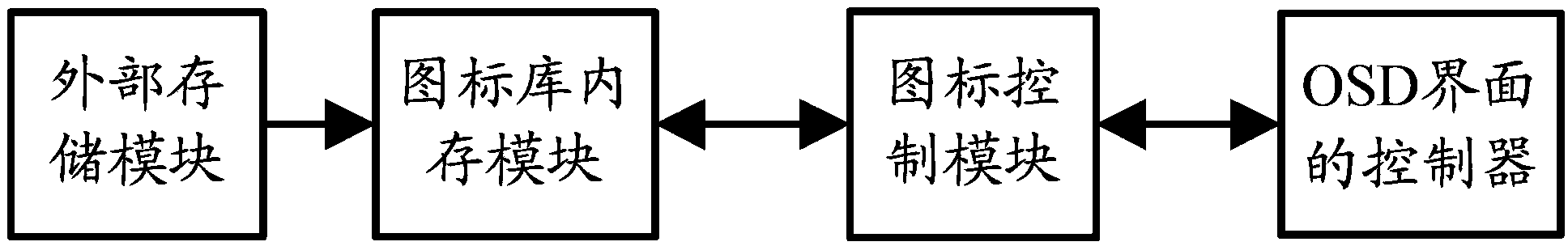
[0050] Such as figure 1 As shown, it is a schematic structural diagram of a system for realizing dynamic icon display control on an OSD interface in an electronic device according to the present invention.

[0051] The system for realizing dynamic icon display control on the screen display OSD interface in the electronic equipment in this embodiment includes:

[0052] An external FLASH memory as an external storage module to store all the data of the icons to be displayed;

[0053] An icon library memory module, connected with the external storage module, used to receive and store the icon data required for displaying the current OSD interface transmitted from the external storage module;

[0054] An icon control module is connected between the icon library memory module and the control unit of the OSD in...


PUM


Abstract

The invention relates to a system for realizing display control of dynamic icons on an OSD (on screen display) interface in electronic equipment. The system comprises an external storage module, an icon library internal memory module and an icon control module, the external storage module stores all data of to-be-displayed icons, the icon library internal memory module is connected with the external storage module, and a control unit of the OSD interface reads icon data in the icon library internal memory module through the icon control module. The invention relates to a method for realizing display control of the dynamic icons on the OSD interface in the electronic equipment. By the system and the method, displaying of the dynamic icons on the OSD interface in the electronic equipment can be realized by only utilizing a small-capacity display buffering storage. The system is simple in structure, convenient to use and wide in application range.

Description

technical field [0001] The present invention relates to the field of electronic screen display, in particular to the field of electronic equipment displaying dynamic icons, in particular to a system and method for realizing dynamic icon display control on an OSD interface in an electronic equipment. Background technique [0002] On-screen display technology (on-screen display, OSD), that is, the screen menu adjustment method, generally press the menu (Menu) button to pop up a rectangular menu of information on the display’s various adjustment items, through which you can adjust the display’s various items. Work indicators including color, pattern, geometry, etc. are adjusted to achieve the best use status. Currently on-screen display technology has been widely used in flat-panel TVs, digital cameras, DV machines and other occasions. Its characteristic is to generate some special fonts or graphics on the screen of the display, so that users can get some information. It is c...

Claims


Application Information

Patent Timeline
IPC IPC(8): G06F3/0481
CPCG06F3/04842G06F13/282
Inventor 张铆计艳
Owner CRM ICBG (WUXI) CO LTD
Features
  • R&D
  • Intellectual Property
  • Life Sciences
  • Materials
  • Tech Scout
  • Unparalleled Data Quality
  • Higher Quality Content
  • 60% Fewer Hallucinations
Learn More