Semiconductor device and manufacturing method thereof

A semiconductor and overall technology, applied in semiconductor/solid-state device manufacturing, semiconductor devices, electrical components, etc., can solve problems such as poor performance in sub-threshold regions, and achieve good short-channel effect control effects

Active Publication Date: 2017-05-31
INST OF MICROELECTRONICS CHINESE ACAD OF SCI
View PDF10 Cites 0 Cited by
  • Summary
  • Abstract
  • Description
  • Claims
  • Application Information

AI Technical Summary

Problems solved by technology

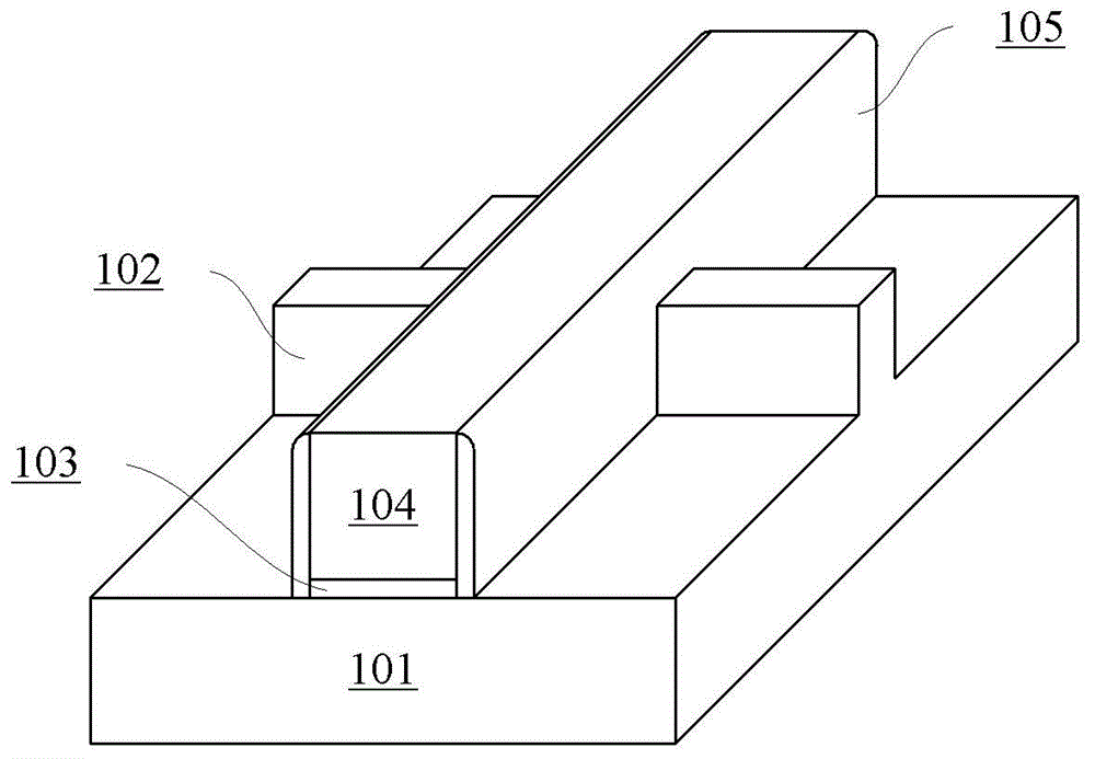
However, where the two branches of the T-shaped fin intersect, such as the region indicated by the arrow in Figure 2(b), the performance of the subthreshold region is poor due to the distance from the gate.

Method used


Image

  • Semiconductor device and manufacturing method thereof
  • Semiconductor device and manufacturing method thereof
  • Semiconductor device and manufacturing method thereof

Examples


Embodiment Construction

[0017] Hereinafter, embodiments of the present disclosure will be described with reference to the drawings. It should be understood, however, that these descriptions are exemplary only, and are not intended to limit the scope of the present disclosure. Also, in the following description, descriptions of well-known structures and techniques are omitted to avoid unnecessarily obscuring the concept of the present disclosure.

[0018] Various structural schematic diagrams according to embodiments of the present disclosure are shown in the accompanying drawings. The figures are not drawn to scale, with certain details exaggerated and possibly omitted for clarity of presentation. The shapes of the various regions and layers shown in the figure, as well as their relative sizes and positional relationships are only exemplary, and may deviate due to manufacturing tolerances or technical limitations in practice, and those skilled in the art will Regions / layers with different shapes, s...


PUM


Abstract

Provided are a semiconductor configuration and a method for manufacturing the same. The semiconductor configuration may comprise: a substrate (301); and a fin. The fin comprises a first portion (302-1) and a second portion (302-2) formed sequentially on the substrate, and the first portion and the second portion are T shaped as a whole. The second portion has a reduced thickness at a region corresponding to the first portion.

Description

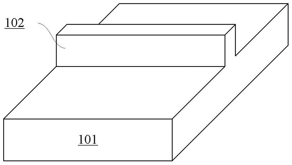
technical field [0001] The present disclosure relates to the field of semiconductors, and more particularly, to a semiconductor arrangement including a fin structure and a method of manufacturing the same. Background technique [0002] As the size of planar semiconductor devices becomes smaller and smaller, the short channel effect becomes more and more obvious. For this reason, three-dimensional semiconductor devices such as FinFETs (Fin Field Effect Transistors) have been proposed. FinFETs include fins formed vertically on a substrate in which the conductive channel of the device can be formed. Since the height of the fin can be increased without increasing its footprint, the current drive capability per unit footprint can be increased. [0003] FIG. 1( a ) shows a conventional fin structure, and FIG. 1( b ) shows a FinFET based on the fin structure shown in FIG. 1( a ). As shown in FIG. 1( a ), fins 102 may be formed on a substrate 101 . In the example shown in FIG. 1...

Claims


Application Information

Patent Timeline
Patent Type & Authority Patents(China)
IPC IPC(8): H01L29/06H01L21/336
CPCH01L29/7853H01L29/66795
Inventor 尹海洲张珂珂
Owner INST OF MICROELECTRONICS CHINESE ACAD OF SCI
Why Eureka
Try Eureka