
low current protection circuit

A protection circuit, low current technology, applied in the direction of emergency protection circuit device, lamp circuit arrangement, circuit device, etc., can solve problems such as damage, PWM signal duty cycle, component heating, etc., to prevent damage, fast abnormal detection, The effect of preventing false detection

Inactive Publication Date: 2016-08-24
SANKEN ELECTRIC CO LTD
View PDF6 Cites 0 Cited by
  • Summary
  • Abstract
  • Description
  • Claims
  • Application Information

AI Technical Summary

Problems solved by technology

[0008] However, when the masking time for masking the abnormality detection is set to be extended, there is a problem that the abnormality detection is performed when the duty ratio of the PWM signal such as continuous operation is large, and the parts may be damaged before entering the low current protection operation. Damaged due to heat, etc.

Method used


Image

  • low current protection circuit
  • low current protection circuit
  • low current protection circuit

Examples


Embodiment Construction

[0037] Next, embodiments of the present invention will be specifically described with reference to the drawings.

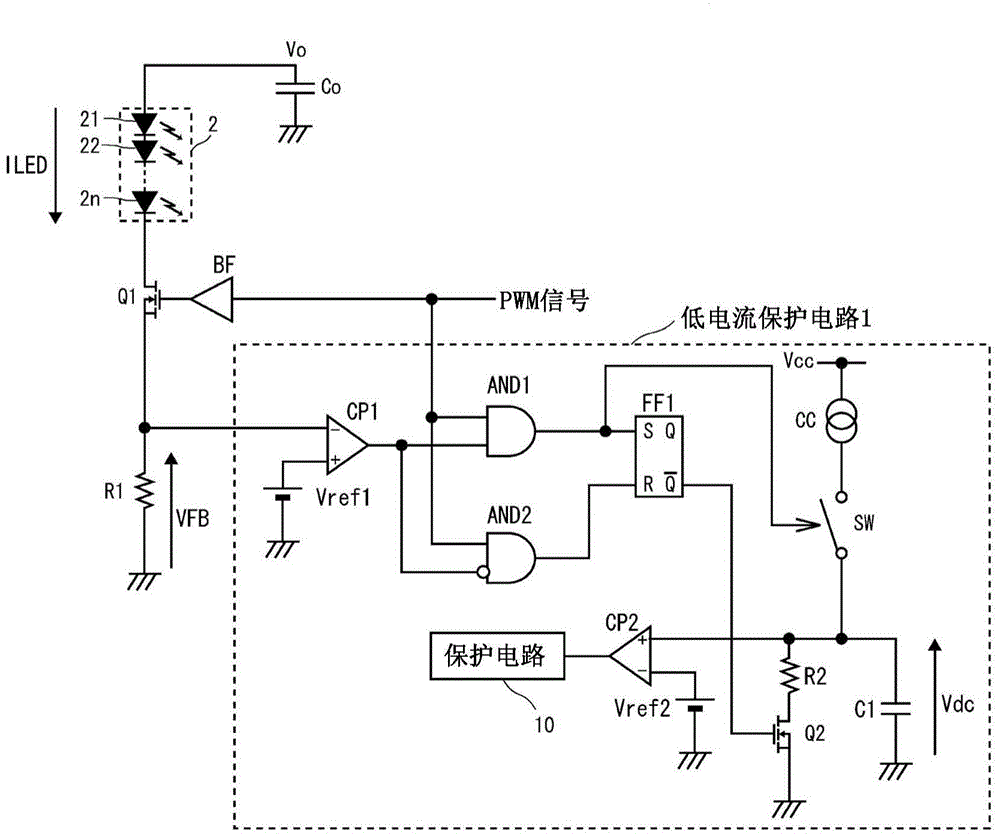
[0038] refer to figure 1 The low-current protection circuit 1 of the present embodiment is installed in a constant-current power supply device (not shown), and the constant-current power supply device is connected in series with a constant current drive based on a PWM signal such as a dimming signal as an external pulse signal ( n represents an arbitrary natural number) LED array 2 composed of LED21-2n. In addition, the PWM signal is an external pulse signal, and is a dimming signal such as a dimming signal (Dimming Signal) that determines the brightness of the LED array 2 based on the duty ratio thereof.

[0039] The LED array 2, the N-type MOSFET (hereinafter referred to as NMOS) Q1, and the detection resistor R1 for detecting the load current flowing through the load, that is, the voltage VFB corresponding to the LED current ILED flowing through the LED array ...


PUM


Abstract

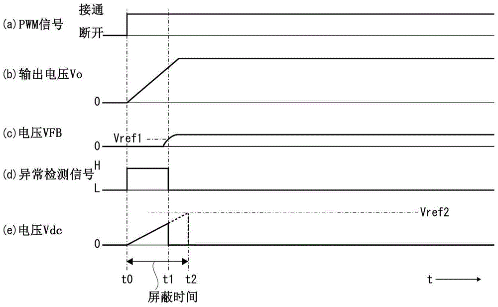
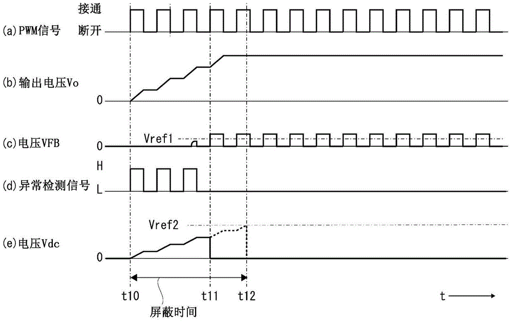
The present invention provides a low-current protection circuit, which can properly set the shielding time for shielding abnormal detection according to the duty cycle of an external pulse signal. The low current protection circuit has: a detection resistor (R1), which detects the LED current ILED; a comparator (CP1), which compares the LED current ILED detected as a voltage VFB by the detection resistor (R1) with a preset reference voltage Vref1. Comparison, detects the reduction of LED current ILED; protection circuit (10), which performs low current protection action when detecting the reduction of LED current ILED by comparator (CP1); and comparator (CP2), which is operated by comparator ( CP1) After detecting the decrease of the LED current ILED, before the masking time set according to the duty ratio of the PWM signal passes, the low-current protection action of the protection circuit (10) is masked.

Description

technical field [0001] The present invention relates to a low-current protection circuit incorporated in a constant-current power supply device that drives a load with a constant current using a pulse signal (hereinafter referred to as a PWM signal) based on PWM control (Pulse Width Modulation: Pulse Width Modulation). . Background technique [0002] LED (light emitting diode: Light Emitting Diode) has a characteristic of changing color tone according to the magnitude of electric current. Therefore, the LED is generally driven with a constant current, and in the case of dimming control, the PWM signal as an external pulse signal is used to drive the LED on / off, and the light quantity is adjusted according to the duty ratio of the PWM signal. [0003] On the other hand, when using a switching power supply as a constant current power supply device that drives a load with a constant current, it is necessary to detect an output current and perform feedback control. As describe...

Claims


Application Information

Patent Timeline
Patent Type & Authority Patents(China)
IPC IPC(8): H05B37/02H05B44/00
CPCH02H3/027H02H3/12H05B45/345H05B45/50Y02B20/30H02H3/26G05D25/02
Inventor 大竹修
Owner SANKEN ELECTRIC CO LTD
Learn More