Drill positioning guider

A positioning guide and positioning block technology, which is applied in the direction of positioning measurement in the boring machine/drilling machine, drilling/drilling equipment, components of the boring machine/drilling machine, etc. To meet the requirements of aircraft assembly accuracy and other issues, to achieve the effect of convenient operation, simple structure, improved processing accuracy and work efficiency

Inactive Publication Date: 2015-02-18
JIANGSU A STAR AVIATION IND
View PDF9 Cites 5 Cited by
  • Summary
  • Abstract
  • Description
  • Claims
  • Application Information

AI Technical Summary

Problems solved by technology

[0004] In order to solve the technical problem that the drilling guide in the prior art only has a guiding function and has no positioning function, and the drilled hole is difficult to be coaxial with the prefabricated nail socket, so it cannot well meet the assembly accuracy requirements of the aircraft. In the way of reverse thinking, starting from the nail socket already made, first cooperate with the prefabricated nail socket through the drilling positioning guide disclosed in the present invention to determine the position of the drilling positioning guide relative to the part to be processed, that is, to determine The po

Method used


Image

  • Drill positioning guider

Examples


Embodiment Construction

[0009] The present invention is described below in conjunction with accompanying drawing:

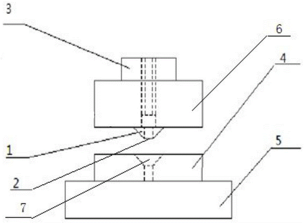
[0010] The drilling positioning guide includes a positioning block 1, a mounting seat 6, and a guide block 3, and is characterized in that: the positioning block 1 is in the shape of a rounded table with a hole in the center, and the small end of the positioning block 1 can be inserted into the prefabricated nail socket In 7, the bottom surface of the small head end is the positioning surface 2, and the positioning surface 2 is perpendicular to the normal direction of the bottom surface of the prefabricated nail pocket 7 of the part to be processed, and the shape of the positioning block 1 matches the shape of the prefabricated nail pocket 7; the center of the guide block 3 is drilled. There is a hole, the center hole of the guide block 3 is matched with the drill bit used in the drilling process, one end of the guide block 3 is connected with the big end of the positioning block 1, the ...


PUM

PropertyMeasurementUnit
Diameteraaaaaaaaaa
Diameteraaaaaaaaaa
Depthaaaaaaaaaa

Abstract

The invention discloses a drill positioning guider, and belongs to the technical field of aerospace manufacturing. The drill positioning guider comprises a positioning block, a mounting seat and a guide block, wherein the positioning block takes the shape of an inverted frustum with a hole in the center; a small head end of the positioning block can be put into a prefabricated nail hole; the bottom surface of the small head end is a positioning surface; the positioning surface is perpendicular to the normal direction of the bottom surface of the prefabricated nail hole of a to-be-machined part; the shape of the positioning block is matched with the contour of the prefabricated nail hole; the hole is drilled in the center of the guide block; the central hole of the guide block is matched with a drill bit used for machining the drill hole; one end of the guide block is connected with a big head end of the positioning block, and the central hole is concentric; the component which is formed by connecting the guide block with the positioning block is named as a positioning guide body; the positioning guide body is fixedly arranged on a mounting seat; the axis of the positioning guide body is in the same direction as the normal direction of the positioning surface of the positioning block. According to the drill positioning guider, the machining precision and the working efficiency of the hole can be greatly improved, and the production cost is reduced; the drill positioning guider has a simple structure, is convenient to operate and can be widely popularized in production.

Description

technical field [0001] The invention belongs to the technical field of aviation manufacturing, and in particular relates to a drilling positioning guide used in the drilling process. Background technique [0002] The currently used drilling guide (also known as drilling guide sleeve) is mainly through the tight fit between the bottom surface of the locator and the surface of the part to be processed to ensure that the drilling direction is in the same direction as the normal direction of the surface of the part to be processed. . When drilling, it is necessary to ensure that the bottom surface of the locator is in full contact with the surface of the part to be processed, and it is also required that the part to be processed has a guide hole that has been determined in the correct position. [0003] In actual work, sometimes it is necessary to drill the initial hole on the part to be processed through the corresponding positioning drilling device and then process the hole r...

Claims


Application Information

Patent Timeline
IPC IPC(8): B23B49/02
CPCB23B49/02
Inventor 王洪亮孙海波于天池
Owner JIANGSU A STAR AVIATION IND
Why Eureka
Try Eureka