Laser scribing device for photovoltaic cells

A photovoltaic cell and laser scribing technology, applied in laser welding equipment, circuits, electrical components, etc., can solve the problems of high-quality products connected, different force, product cost increase, etc., to solve the problem of debris and cracks, The effect of avoiding electrical stress and improving production efficiency

Active Publication Date: 2017-05-31
XINYANG NORMAL UNIVERSITY
View PDF11 Cites 0 Cited by
  • Summary
  • Abstract
  • Description
  • Claims
  • Application Information

AI Technical Summary

Problems solved by technology

However, in actual operation, due to the different parts of the fingers of the manual operation, and the force of different fingers is different, it is normal for the stress field distribution inside the photovoltaic cells to be uneven when the sheets are separated.
Therefore, there are often irregular fragments or irregular cracks when the artificial sheets are separated, and the high quality of the cut photovoltaic cells cannot be guaranteed.
The debris problem in the existing technical solutions will result in low yield, high product cost, hidden cracks and other problems will cause a significant decline in the quality and reliability of photovoltaic products, and hidden cracks will cause thermal stress, electrical stress and chemical stress of photovoltaic cells. Stress concentration points are easy to form defects such as hot spots and black lines, and become hidden dangers in photovoltaic applications
[0003] At the same time, there is a bare conductive substance on the edge of the cell cut by the existing laser scribing device, which is easy to produce a tip discharge effect and cause electrical stress.
[0004] Therefore, at present, it is difficult to connect small sliced ​​batteries with high-quality products, and laser slicing is the key technical bottleneck

Method used


Image

  • Laser scribing device for photovoltaic cells
  • Laser scribing device for photovoltaic cells
  • Laser scribing device for photovoltaic cells

Examples


Embodiment Construction

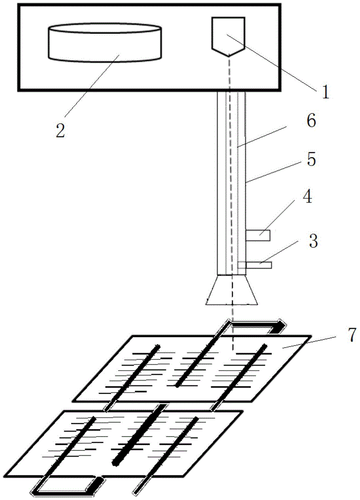
[0021] Such as figure 1 As shown, a laser scribing device for photovoltaic cells includes a laser source 1, an inner tube structure 6, an outer tube structure 5, an oxidizing gas source, an air extraction system and a scribing workbench 8, and the outer tube structure 5 is set Outside the inner tube structure 6, the end of the outer tube structure 5 close to the photovoltaic cell 7 is a bell mouth, and the beam emitted by the laser source 1 passes through the inner tube structure 6 and then shines on the scribing table 8 where the photovoltaic cell 7 is placed , the inner pipe structure 6 has a vent pipe 3 for connecting the oxidizing gas source, the oxidizing gas of the oxidizing gas source enters the inner pipe structure 6 through the vent pipe 3, and is sprayed to the front of the laser scribing through the inner pipe structure 6, On the outer pipe structure 5 there is an air extraction pipe 4 for connecting the air extraction system, the air extraction system is connected ...


PUM


Abstract

The invention relates to a laser scribing device for photovoltaic cells. The laser scribing device for the photovoltaic cells comprises a laser source, an internal tube structure, an external tube structure, an oxidizing gas source, a gas exhausting system and a scribing workbench, wherein the external tube structure sleeves the outer part of the internal tube structure; a light beam emitted by the laser source penetrates through the internal tube structure and irradiates the scribing workbench; oxidizing gas of the oxidizing gas source is jetted to the front tip of the laser scribing device through the internal tube structure; the gas exhausting system exhausts gas through the external tube structure. The laser scribing device for the photovoltaic cells has the benefits that through the automatic laser scribing, the production efficiency is greatly improved, and due to avoidance from manual cell separation, the problems of fragments and hidden cracks caused by an artificial breaking way can be completely solved; in a way of oxidizing cleaning while cutting, conductive substances on the edge of a cut wafer are insulated so as to avoid electrical stress during tip electricity generation of adjacent wafers; the laser scribing device can perform scribing and separation before and after interconnection of the photovoltaic cells.

Description

technical field [0001] The invention relates to the technical field of scribing photovoltaic cells, in particular to a laser scribing device for photovoltaic cells. Background technique [0002] The existing laser scribing technology only creates a deep groove on the surface of the silicon wafer of the photovoltaic cell, and then uses this deep groove as a guide to separate the two parts after cutting by manual breaking. Generally speaking, after the cell is subjected to external force, it will break and separate along the deep groove part of the laser scribe with the most serious defects. However, in actual operation, due to the different parts of the fingers in manual operation, and the different forces of different fingers, it is normal for the stress field distribution inside the photovoltaic cells to be uneven when the sheets are separated. Therefore, there are often irregular fragments or irregular cracks when the artificial sheets are separated, which cannot guarante...

Claims


Application Information

Patent Timeline
Patent Type & Authority Patents(China)
IPC IPC(8): B23K26/364B23K26/402B23K26/12B23K26/142B23K26/70H01L21/78
CPCB23K26/123B23K26/14B23K2101/40H01L21/78
Inventor 黄强黄家烨冯岩程涛韩会丽夏燕杰孟蓝翔陈华刘江峰耿晓菊彭琪刘盟盟余本海刘彦明卢克平
Owner XINYANG NORMAL UNIVERSITY
Why Eureka
Try Eureka