Treatment method for blast furnace melting slag

A processing method and slag melting technology, which is applied in the field of blast furnace slag processing, can solve the problems of inability to process liquid blast furnace slag, slag glass rate less than 80%, and spiral blade failure, so as to save liquid rotary connection equipment, Ease of maintenance and continuous operation, and the effect of effective waste heat recovery

Inactive Publication Date: 2015-02-18
INNER MONGOLIA UNIV OF SCI & TECH
View PDF7 Cites 7 Cited by
  • Summary
  • Abstract
  • Description
  • Claims
  • Application Information

AI Technical Summary

Problems solved by technology

The analysis of the embodiment of the patent US4330264 shows that although the surface quenching rate of the slag treated by this device is very high and the glassy rate on the surface of the slag is very high, the inside of the slag layer has not been quenched, and the overall glassy rate of the slag is less than 80%. %; and because the inside of the slag layer is not sufficiently cooled, the hardening temperature is not lowered to 850°C during mechanical peeling, and the peeled slag layer will continue to bond together to form a blocky slag, which seriously affects the later use
The slag cooler cannot handle liquid blast furnace slag, because the molten slag will stick to the blades during cooling and solidification, making the helical blades useless

Method used


Image

  • Treatment method for blast furnace melting slag
  • Treatment method for blast furnace melting slag
  • Treatment method for blast furnace melting slag

Examples


Embodiment 1

[0048] A blast furnace slag with an average thermal conductivity of 0.75W / (m·K) is processed.

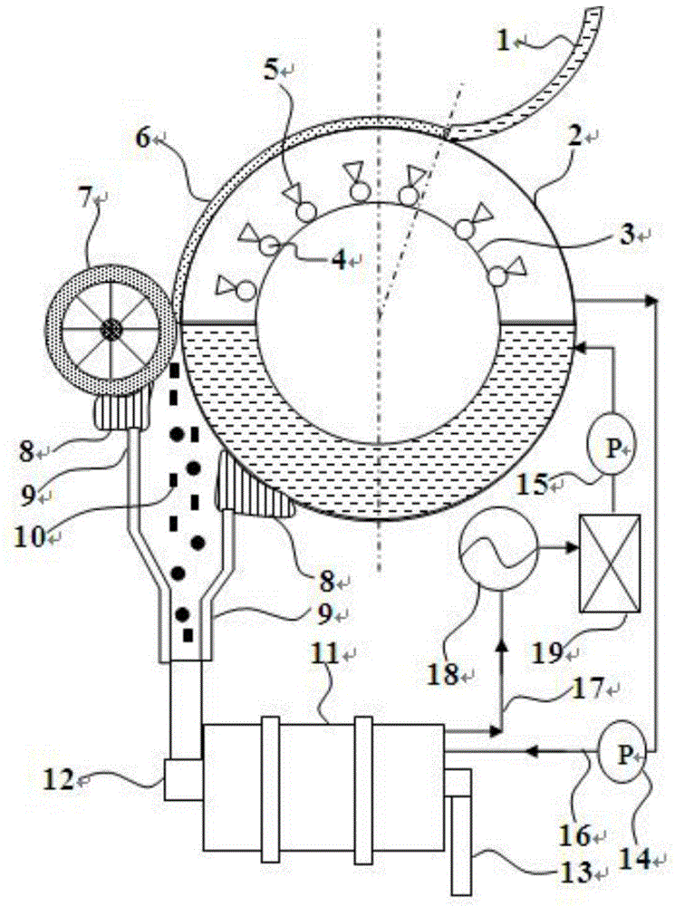
[0049] The outer diameter of the inner-cooled single drum is 1000mm, the thickness is 10mm, and the speed is 3.5 rpm; the outer diameter of the inner-cooled single drum is 300mm, the thickness is 5mm, and the gap between the inner cylinder and the outer cylinder is 350mm; The outer diameter of the drum is 400mm, the wall thickness is 50mm, the speed is 20 rpm, and the outer surface is roughened; a certain type of square water mist nozzle is used, the nozzle aperture is 15mm, the water inlet pressure is 3bar, the spray angle is 60°, and the flow rate is 4.5L / min, the distance between the nozzle opening and the inner surface of the outer cylinder is 250mm, there are 5 cooling water pipes, and each pipe is equipped with 22 nozzles, such as figure 1 As shown, the arrangement is denser on the side of the slag layer to ensure the formation of continuous water mist on the inner surface of ...

Embodiment 2

[0052] A blast furnace slag with an average thermal conductivity of 0.2W / (m·K) is processed.

[0053] The outer diameter of the inner cooling single drum is 3000mm, the thickness is 20mm, and the speed is 1.9 rpm; the outer diameter of the inner cooling single drum is 1400mm, the thickness is 15mm, and the gap between the inner cylinder and the outer cylinder is 800mm; The outer diameter of the drum is 1000mm, the wall thickness is 100mm, the speed is 15 rpm, and the outer surface is engraved with grooves with a width of 0.5mm and a depth of 1mm every 2mm along the axial direction; a certain type of solid rectangular water mist nozzle is used, and the nozzle aperture is 25mm , the water inlet pressure is 1bar, the spray angle is 90° on the long side and 60° on the short side, the flow rate is 5.8L / min, the distance between the nozzle opening and the inner surface of the outer cylinder is 300mm, and there are 8 cooling water pipes arranged at equal intervals. Equipped with 18 n...


PUM

PropertyMeasurementUnit
diameteraaaaaaaaaa
thicknessaaaaaaaaaa
diameteraaaaaaaaaa

Abstract

The invention relates to the technical field of treating furnace slag during pig iron melting, and particularly provides a treatment method for blast furnace melting slag. According to the treatment method, a blast furnace melting slag treatment device is utilized and controlled. Through utilizing the treatment method, not only can the treatment requirements on shock cooling, granulation and residual heat utilization of the blast furnace slag be met, but also the use of high-pressure vapor or inflammable organic matters can be avoided.

Description

technical field [0001] The invention relates to the technical field of slag treatment in pig iron smelting, and in particular provides a treatment method for blast furnace slag. Background technique [0002] Slag is a by-product in the production of metallurgical industry, among which the blast furnace slag produced by pig iron smelting occupies a large proportion. Dry blast furnace slag treatment technology needs to solve two main problems: one is rapid cooling to form a glassy structure and granulate as much as possible, and the other is the utilization of waste heat in the cooling process. The discharge temperature of liquid blast furnace slag is about 1450°C. If the quenching condition can be met during the cooling process, especially around 1200°C, glassy slag will be formed; when the temperature of the slag is lower than 850°C, it will be in a hardened state and can be crushed. It is no longer bonded; the effectively granulated slag with a glassy ratio greater than 90...

Claims


Application Information

Patent Timeline
Patent Type & Authority Applications(China)
IPC IPC(8): C21B3/08
CPCC21B3/06C21B3/08
Inventor 李永治赵增武田红晓杨文策
Owner INNER MONGOLIA UNIV OF SCI & TECH
Why Eureka
Try Eureka