Reinforced plastic cable wells

A technology for strengthening structures and cable wells, applied in the field of electric power construction or construction, can solve problems such as strength reduction, waste of clay resources, easy corrosion and peeling, etc., to absorb and buffer vibration and pressure, reduce the impact of road traffic, acid resistance and good alkaline effect

Active Publication Date: 2018-01-05
KUNMING PURETOWN ENVIRONMENTAL TECH
View PDF10 Cites 0 Cited by
  • Summary
  • Abstract
  • Description
  • Claims
  • Application Information

AI Technical Summary

Problems solved by technology

[0004] However, practice has proved that the existing brick or concrete cable wells buried in the ground are easily corroded and peeled off by wet soil, water vapor, moisture immersion, acid, alkali and salt erosion, and lose waterproof ability, easy to infiltrate, poor durability, and reduced strength. , easily damaged; since cable wiring and cable wells are set along both sides of the road, once such a cable well is damaged, it will affect the smooth traffic of urban roads and is not conducive to the protection of groundwater resources.
[0005] And a large number of clay bricks are used to cause a waste of clay resources, which does not comply with environmental protection policies. Moreover, with the current structure, when inspecting cables, the bricks must be knocked off before inspection, which is a waste of time and labor. Laying bricks again will cause a lot of waste
Or in the structure of using the manhole cover to close the cable well, the structural strength of the manhole cover is insufficient, and it is inconvenient to use

Method used


Image

  • Reinforced plastic cable wells
  • Reinforced plastic cable wells
  • Reinforced plastic cable wells

Examples


Embodiment Construction

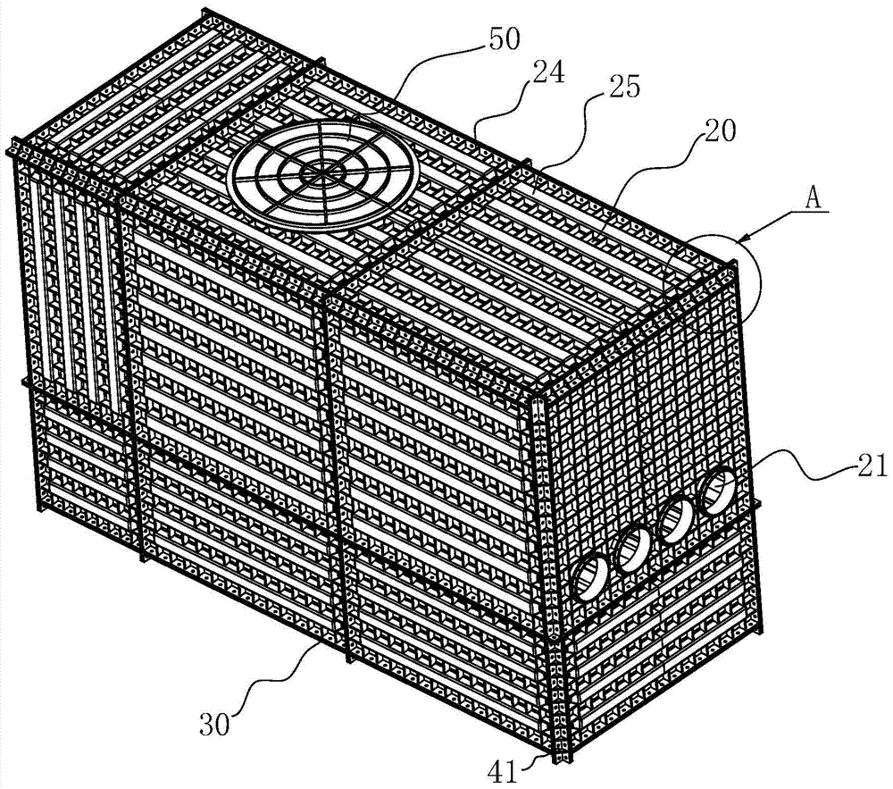
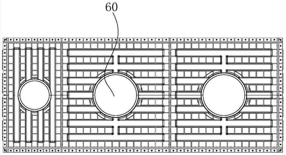
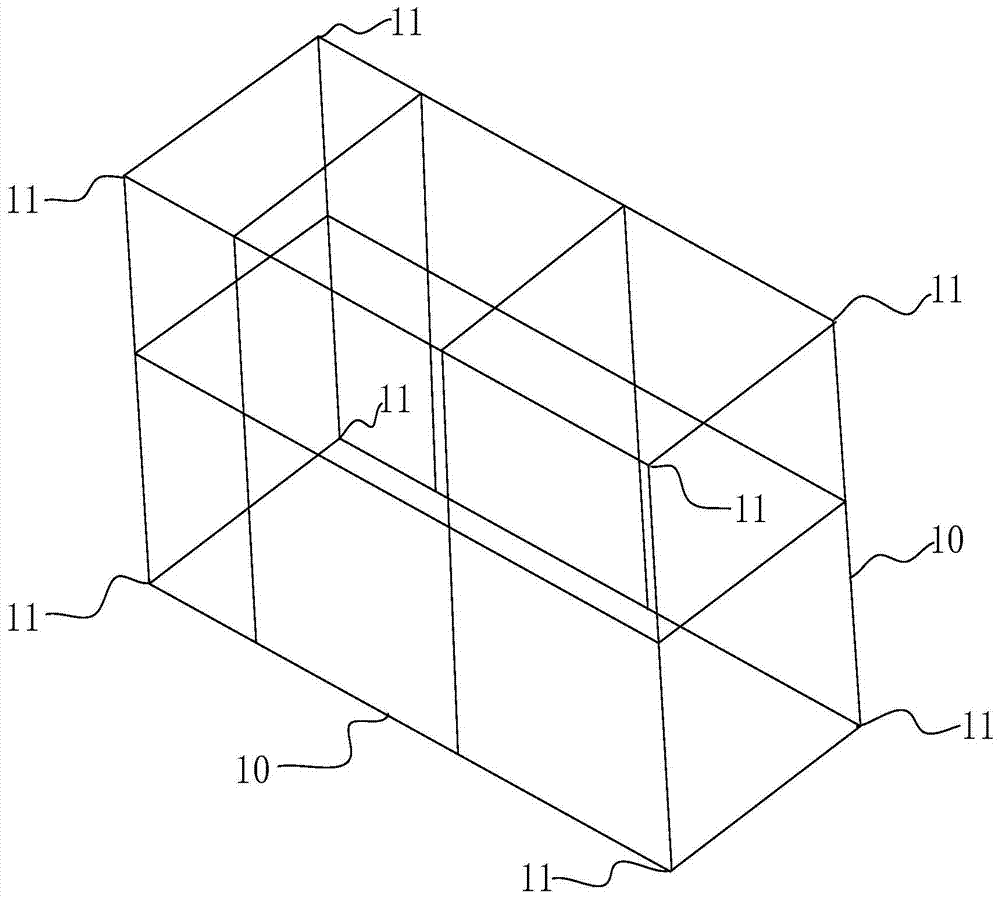
[0017] Such as figure 1 , 2 , The plastic cable well of the reinforced structure shown in 3 and 4, the cable well includes a box-shaped well body, and the improvement of the present invention is that the well body includes internal such as image 3 The metal frame shown and set outside the metal frame such as figure 1 See the casing, the casing is made of plastic material, the casing is provided with a wire inlet 21, and one end opposite to the wire inlet 21, that is, the side opposite to the wire inlet 21 in the length direction of the well body is set Outlet hole, well body upper side is provided with manhole 50 or hand hole, and general large well body is exactly manhole, and small well body is exactly hand hole. The outer surface of the shell is uniformly staggered with reinforcing ribs, and the staggered setting of the reinforcing ribs is criss-cross or obliquely staggered, which can better support the shell and strengthen the structure; such ribs can also be set inside...


PUM


Abstract

The invention relates to the technology of electric power construction or construction, in particular to an electric cable well which is acid-resistant, alkali-resistant and durable. The electric cable well comprises a box-shaped well body, wherein the well body comprises a metal frame and a shell; the metal frame is arranged in the well body; the shell is arranged outside the metal frame and is made of plastic; a wire inlet, a wire outlet and a human hole or a hand hole are formed in the shell; reinforcing ribs are uniformly arranged in the shell and / or on the outer surface of the shell in a staggering mode. Due to the fact that the electric cable well is of the structure that the metal frame is arranged in the well body and the shell is arranged outside the metal frame, the metal frame supports the shell, and meanwhile, the reinforcing ribs are arranged on the outer surface of the shell in a staggering mode, so the structural strength of the shell is further guaranteed. The electric cable well with such structure is reliable in structural strength; meanwhile due to the fact that the reinforcing ribs are arranged on the plastic shell and the shell, the shell has certain flexibility, and shock and pressure can be better absorbed and buffered; the electric cable well has the characteristics of high water draining efficiency, acid resistance, alkali resistance, salt corrosion resistance, suitability for multiple geological conditions, high earthquake resistance and long service life; important economic and social benefits are achieved.

Description

[0001] This application is a divisional application of the invention patent with the application number: 201210046209.2 and the patent name: "A Plastic Power Cable Well". The original application date: 2012-2-28. technical field [0002] The invention relates to electric power construction or construction technology, in particular to a cable well. Background technique [0003] The cable well is an underground inspection well that plays the role of installation or maintenance during construction and after the completion of the project in the cable laying project. It is generally divided into manhole well and hand hole well. The manhole well is relatively large, and people can go down into the well for construction operations. The hand hole well is generally relatively small, and only the hand can be reached in for operation. It is generally used on branch lines, and there are not many cables passing through the well. , easy threading. Most of the traditional cable wells ar...

Claims


Application Information

Patent Timeline
Patent Type & Authority Patents(China)
IPC IPC(8): E02D29/12
CPCE02D29/12E02D29/121E02D2200/1642E02D2300/0006E02D2300/0031
Inventor 童薇
Owner KUNMING PURETOWN ENVIRONMENTAL TECH
Why Eureka
Try Eureka