Low-friction air valve oil seal
A valve oil seal and low-friction technology, which is applied in the direction of lift valves, engine components, machines/engines, etc., can solve problems such as carbon deposits and large oil leakage, reduce content, ensure normal operation, and accurately control oil leakage Effect
- Summary
- Abstract
- Description
- Claims
- Application Information
AI Technical Summary
Problems solved by technology
Method used
Image
Examples
Embodiment 1
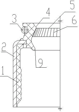
[0033] Embodiment 1, a kind of low-friction valve oil seal, such as figure 1 , the elastic sealing body 1 wraps the support frame 2, the elastic sealing body 1 is provided with a sealing lip, the sealing lip is the main sealing lip 4 and the air lip 9, the outer side of the main sealing lip 4 is provided with a spring 3, and the annular sealing surface formed by the main sealing lip 4 A strip-shaped axial main lip annular band 5 is provided on the main lip annular band 5, and an annular rib or groove 6 is arranged on the main lip annular band 5. The height of the rib or the depth of the groove is 0.02--0.20 mm. This embodiment adopts A groove 6 with a semicircular cross section and a depth of 0.2 mm constitutes a structure of the present invention.
Embodiment 2
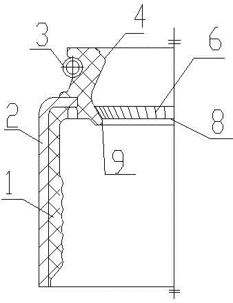
[0034] Embodiment 2, a kind of low-friction valve oil seal, such as figure 2 , is on the basis of Example 1. Compared with Example 1, only a strip-shaped axial air lip annular band 8 is provided on the annular sealing surface formed by the air lip 9, and an annular air lip annular band 8 is provided with an annular Ribs or grooves 6, the main sealing lip 4 is not provided with an axial main lip annular zone 5, this embodiment adopts ribs 6 with a trapezoidal cross section, the height of ribs 6 is 0.1 mm, and the rest of the structure is the same as that of embodiment 1.
example 3
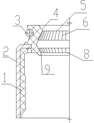
[0035] Example 3, a low-friction valve oil seal, such as image 3 As shown, on the basis of Example 1, on the annular sealing surface formed by the main sealing lip 4 and the air lip 9, strip-shaped axial main lip annular bands 5 and air lip annular bands 8 are respectively provided, and the main lip annular band 5 Annular ribs or grooves 6 are arranged on the annular belt 8 of the air lip. This embodiment adopts ribs 6 with a triangular cross-section. The height of ribs 6 is 0.02 mm.
PUM
 Abstract
Description
Claims
Application Information
 - R&D
- Intellectual Property
- Life Sciences
- Materials
- Tech Scout
- Unparalleled Data Quality
- Higher Quality Content
- 60% Fewer Hallucinations
Browse by: Latest US Patents, China's latest patents, Technical Efficacy Thesaurus, Application Domain, Technology Topic, Popular Technical Reports.
© 2025 PatSnap. All rights reserved.Legal|Privacy policy|Modern Slavery Act Transparency Statement|Sitemap|About US| Contact US: help@patsnap.com


