
Fan control circuit with functions of controlling temperature and preventing touch and electric leakage

A fan control and circuit technology, applied in pump control, circuit device, engine control, etc., can solve problems such as aging power cord, children's fingers being scratched or cut, and safety hazards.

Inactive Publication Date: 2015-02-18
BINZHOU UNIV +1
View PDF9 Cites 10 Cited by
  • Summary
  • Abstract
  • Description
  • Claims
  • Application Information

AI Technical Summary

Problems solved by technology

[0005] Furthermore, since there are large gaps on the front and rear covers of the fan, naughty children will put their fingers into the fan cover during the use of the fan, which is very prone to accidents where children touch the fan blades by mistake, and in severe cases it will Scratches or cuts off children's fingers, which poses a certain safety hazard
At the same time, since the fans are powered by 220V AC, years of use will easily lead to aging of the power cord, so that the electric fan shell is connected to the 220V AC, so that the electric fan shell will be charged, which is prone to electric shock accidents

Method used


Image

  • Fan control circuit with functions of controlling temperature and preventing touch and electric leakage
  • Fan control circuit with functions of controlling temperature and preventing touch and electric leakage
  • Fan control circuit with functions of controlling temperature and preventing touch and electric leakage

Examples


Embodiment Construction

[0017] The present invention will be further described below in conjunction with the accompanying drawings and embodiments.

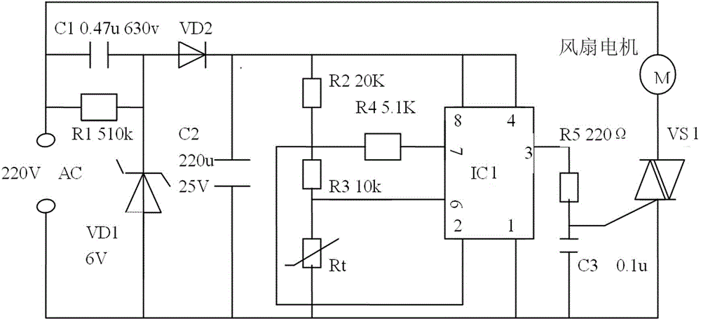
[0018] Such as figure 1 As shown, the schematic diagram of the fan control circuit with temperature control, anti-touch and leakage current of the present invention is given, which includes voltage regulator tube VD1, diode VD2, 555 timer IC1, thermistor Rt and bidirectional thyristor VS1, The bidirectional thyristor VS1 is connected in series with the fan motor M and then connected to both ends of the 220V alternating current. By controlling the on-off state of the bidirectional thyristor VS1, the running state of the fan motor M can be controlled. The voltage regulator tube VD1 is connected in series with the resistor R1 and then connected to both ends of the 220V AC power supply. The model of the voltage regulator tube VD1 is 6V; the capacitor C2 is connected in series with the diode VD2 and connected to both ends of the voltage regulator tube VD1 to...


PUM


Abstract

The invention discloses a fan control circuit with functions of controlling the temperature and preventing touch and electric leakage. The fan control circuit comprises a voltage stabilizing tube VD1, a heat-sensitive resistor Rt, a 555 timer IC1 and a two-way thyristor VS1. The fan is characterized in that a pin 1 of the 555 timer IC1 is connected to one end of a capacitor C2, a pin 4 and a pin 8 of the 555 timer IC1 are connected to the other end of the capacitor C2 simultaneously; the low triggering end of the 555 timer IC1 is connected to the connecting position of a resistor R2 and a resistor R3, the high triggering end of the 555 timer IC1 is connected to the connecting position of the heat-sensitive resistor and a resistor R3, the discharging end of the 555 timer IC1 is connected between the resistor R3 and the resistor R2 by a resistor R4, and the output end of the 555 timer IC1 is connected with the control electrode of the two-way thyristor VS1 by a resistor R4. The fan control circuit disclosed by the invention has the advantages that the starting and the stopping of a fan can be controlled according to the external temperature, so that not only the comfort is ensured, but also the electric energy is saved; the fan control circuit also has the functions of preventing from touching fan blades and protecting from electric leakage, the beneficial effect is obvious, and the application and the promotion are convenient.

Description

technical field [0001] The present invention relates to a fan control circuit, more specifically, to a fan control circuit with temperature control, touch prevention and electric leakage. Background technique [0002] The main part of the electric fan is an AC motor. The rotor is composed of magnets, fan blades and shafts. The stator is composed of silicon steel sheets, spools and bearings. The N pole and S pole of the magnet are controlled by the circuit to conduct the coil to generate internal excitation to make the rotor rotate. The form of energy conversion is that electrical energy is mainly converted into mechanical energy, and the airflow is generated under the rotation of the fan blades to cool the human body; at the same time, because the coil has resistance, it is inevitable that a part of the electrical energy will be converted into heat energy. [0003] When the electric fan is working (assuming there is no heat transfer between the room and the outside world), ...

Claims


Application Information

Patent Timeline
IPC IPC(8): F04D27/00H02H5/12H02H3/04
CPCF04D27/00F04D27/008F05D2270/312H02H3/04H02H5/12
Inventor 邢进程岳雷赵华文
Owner BINZHOU UNIV
Learn More