Light-emitting diode (LED) module

A technology of LED modules and lens groups, which is applied in lighting and heating equipment, semiconductor devices of light-emitting elements, point light sources, etc. The effect of deviation, avoiding breakage, good luminous effect

Active Publication Date: 2015-02-18
HANGZHOU HPWINNER OPTO CORP
View PDF11 Cites 5 Cited by
  • Summary
  • Abstract
  • Description
  • Claims
  • Application Information

AI Technical Summary

Problems solved by technology

[0004] Sealing rings are usually used to realize the sealing between the lens group and the radiator, and the radiator and the lens group are connected through a connector. However, in the prior art, the connector is generally arranged on the outer side of the radiator and the lens group. And it is located on the outside of the sealing ring; when the radiator and the lens group are connected through the connecting piece, the edge of the lens group is subjected to a pulling force towards the side of the radiator, and the supporting force of the sealing ring on the lens group, so that the lens group is deformed , causing the middle part of the lens group to bulge, resulting in optical deviation and affecting the lighting effect
[0005] In addition, in the prior art, the connecting piece between the radiator and the lens group is arranged outside, and the connecting piece is easy to break under the wind and sun, posing a safety hazard

Method used


Image

  • Light-emitting diode (LED) module
  • Light-emitting diode (LED) module
  • Light-emitting diode (LED) module

Examples


Embodiment Construction

[0039] The invention will be described in more detail hereinafter with reference to the accompanying drawings showing embodiments of the invention. However, this invention may be embodied in many different forms and should not be construed as limited to the embodiments set forth herein. Rather, these embodiments are provided so that this disclosure will be thorough and complete, and will fully convey the scope of the invention to those skilled in the art. In these drawings, the size and relative sizes of layers and regions may be exaggerated for clarity.

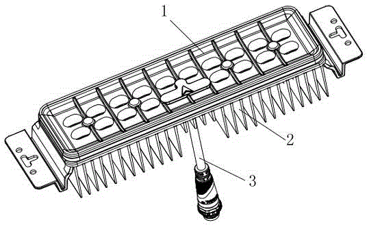
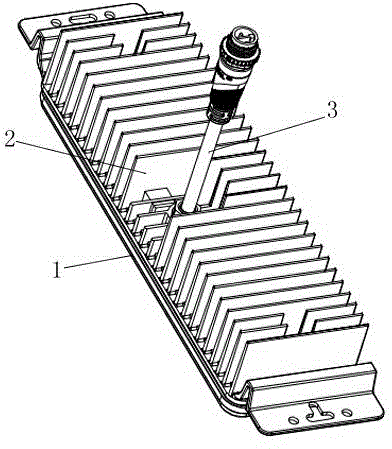
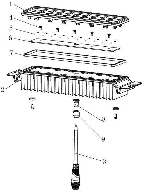
[0040] refer to Figure 1-7 , the present invention provides an LED module, including a lens group 1, a heat sink 2 and a light-emitting module, the lens group 1 is covered on the heat sink 2, and the light-emitting module is arranged in the space formed between the lens group 1 and the heat sink 2 Inside.

[0041] The light emitting module includes a substrate 6 and an LED light emitting unit 5 , and the LED light emitti...


PUM


Abstract

The invention provides a light-emitting diode (LED) module, comprising a lens group, a light emitting module and a radiator, wherein the lens group covers the radiator; the light emitting module is arranged between the lens group and the radiator; a circle of sealing ring is arranged between the lens group and the radiator; the lens group is connected with the radiator through a connector; the connector is positioned on the inner side of the sealing ring, and is arranged along a circle of the inner side of the sealing ring, or is arranged in a surrounded region of the sealing ring in a linear manner; the connector comprises a plurality of pairs of fasteners; each pair of fasteners comprises a first fastener and a second fastener, which are matched with each other; the first fasteners are arranged on the lens group; the second fasteners are arranged on the radiator; the first fasteners and the second fasteners are opposite in position. According to the light-emitting diode module, the connector between the lens group and the radiator is arranged on the inner side of the sealing ring, so that the problem of optical deviation due to the fact that the middle part of the lens group is bulged in the prior art is prevented; meanwhile, the problem that the connector is easily damaged when being arranged on the outer side is avoided.

Description

technical field [0001] The invention relates to the technical field of lighting device design, in particular, the design relates to an LED module. [0002] Background technique [0003] LED lamps have the advantages of energy saving, long life, good applicability, short response time, and environmental protection, and are the development direction of the lamp industry. The LED module is an essential part of the LED lamps. Generally, the LED module is composed of a lens group, a light-emitting module and a heat sink. The light-emitting module is set on the heat Between the lens group and the radiator. [0004] Sealing rings are usually used to realize the sealing between the lens group and the radiator, and the radiator and the lens group are connected through a connector. However, in the prior art, the connector is generally arranged on the outer side of the radiator and the lens group. And it is located on the outside of the sealing ring; when the radiator and the lens g...

Claims


Application Information

Patent Timeline
Patent Type & Authority Applications(China)
IPC IPC(8): F21S2/00F21V31/00F21V17/10F21Y101/02
CPCF21K9/20F21V17/164F21V31/005F21Y2105/10F21Y2115/10
Inventor 陈凯黄建明
Owner HANGZHOU HPWINNER OPTO CORP
Why Eureka
Try Eureka