Microseism event positioning method and device based on automatic scanning of longitudinal and transverse wave energy

An automatic scanning and micro-seismic technology, applied in the direction of seismic signal processing, etc., can solve problems such as large signal-to-noise ratio differences, huge data volume, and timeliness impact of fracturing construction plans

Active Publication Date: 2015-02-18
BC P INC CHINA NAT PETROLEUM CORP +1
View PDF6 Cites 10 Cited by
  • Summary
  • Abstract
  • Description
  • Claims
  • Application Information

AI Technical Summary

Problems solved by technology

[0002] Fracturing microseismic monitoring signals are affected by rock fracture energy and background noise, and the signal-to-noise ratio of received signals varies greatly, which has a great impact on the arrival time of picking up microseismic events and real-time data processing
[0003] The fracturing microseismic monitoring signal has a long duration and a huge amount of data. The microseismic events with high signal-to-noise ratio can be accurately picked up by the automatic picking algorithm, but the microseismic events with medium and low signal-to-noise ratios can be picked up through automatic picking. It cannot achieve better accuracy, and has a greater impact on the direction calculation and positioning results of microseismic events
On-site real-time micro-seismic signal processing requires manual interactive correction of micro-seismic first-arrival pick-ups that do not meet the standards to meet industrial processing standards, which greatly delays the real-time performance of micro-seismic signal processing results. The timeliness of the cracked construction plan has been affected

Method used


Image

  • Microseism event positioning method and device based on automatic scanning of longitudinal and transverse wave energy
  • Microseism event positioning method and device based on automatic scanning of longitudinal and transverse wave energy
  • Microseism event positioning method and device based on automatic scanning of longitudinal and transverse wave energy

Examples


Embodiment Construction

[0049] The following will clearly and completely describe the technical solutions in the embodiments of the present invention with reference to the accompanying drawings in the embodiments of the present invention. Obviously, the described embodiments are only some, not all, embodiments of the present invention. Based on the embodiments of the present invention, all other embodiments obtained by persons of ordinary skill in the art without making creative efforts belong to the protection scope of the present invention.

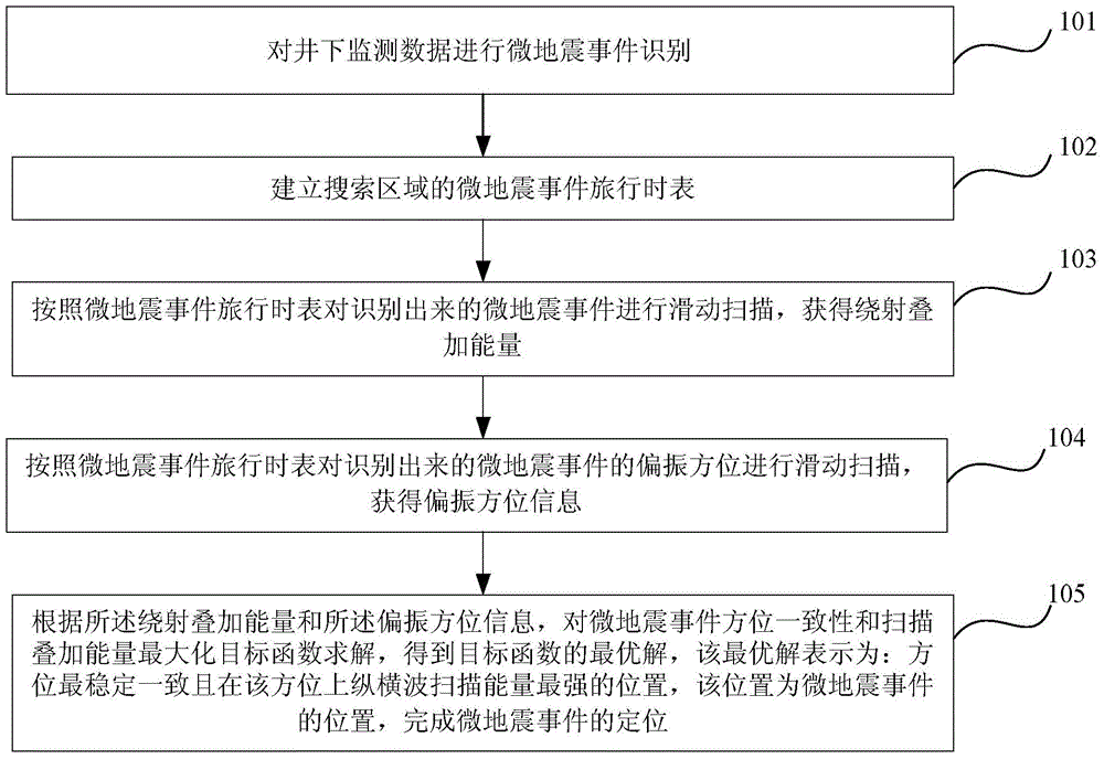
[0050] The working principle of the technical solution of the present invention is as follows: in positioning processing of fracturing micro-seismic monitoring data, the azimuth and position of micro-seismic events are reversed and positioned by means of longitudinal and transverse wave scanning. First, event identification is performed on the original records, the travel time table of microseismic events in the search area is established, the polarization azim...


PUM


Abstract

The invention relates to a microseism event positioning method and device based on automatic scanning of longitudinal and transverse wave energy. The method includes the steps that microseism event recognition is carried out on underground monitoring data; a microseism event travel-time table of a searched area is built; sliding scanning is carried out on a recognized microseism event according to the microseism event travel-time table, and accordingly diffraction stacked energy is obtained; sliding scanning is carried out on the polarization direction of the recognized microseism event according to the microseism event travel-time table, so information of the polarization direction is obtained; an objective function of microseism event direction consistence and scanned and stacked energy maximization is solved according to the diffraction stacked energy and the information of the polarization direction, and accordingly an optimal solution of the objective function is obtained. The optimal solution represents the position where direction stability and consistence are best and longitudinal and transverse wave scanned energy is strongest in the direction and the position is where the microseism event happens.

Description

technical field [0001] The invention relates to the technical field of fracturing microseismic monitoring data, in particular to a method and device for locating microseismic events based on automatic scanning of longitudinal and shear wave energy. Background technique [0002] Fracturing microseismic monitoring signals are affected by rock fracture energy and background noise, and the signal-to-noise ratio of received signals varies greatly, which has a great impact on the arrival time of picking up microseismic events and real-time data processing. [0003] The fracturing microseismic monitoring signal has a long duration and a huge amount of data. The microseismic events with high signal-to-noise ratio can be accurately picked up by the automatic picking algorithm, but the microseismic events with medium and low signal-to-noise ratios can be picked up through automatic picking. Failure to achieve better accuracy will have a greater impact on the direction calculation and ...

Claims


Application Information

Patent Timeline
Patent Type & Authority Applications(China)
IPC IPC(8): G01V1/28
Inventor 容娇君李彦鹏徐刚储仿东刘博衡峰刘腾蛟张固澜张彦斌吴俊军
Owner BC P INC CHINA NAT PETROLEUM CORP
Why Eureka
Try Eureka