Sensitivity-based reactive compensation and location optimization method

A sensitivity method and voltage sensitivity technology, applied in special data processing applications, instruments, electrical digital data processing, etc., can solve the problems of not being able to maintain and adjust the terminal voltage level of the machine, system active power imbalance, accident expansion, etc., to improve acceptance and transmission capacity, increase the power on the grid, and reduce the effect of curtailed wind

Inactive Publication Date: 2015-02-18
STATE GRID CORP OF CHINA +3
View PDF2 Cites 10 Cited by
  • Summary
  • Abstract
  • Description
  • Claims
  • Application Information

AI Technical Summary

Problems solved by technology

At present, the low-voltage tolerance of the wind turbine itself is very limited. At this time, the wind turbine often adopts the method of automatic cut-off for its own protection, which causes the active power imbalance of the system and affects the stability of the system; at the same time, the asynchronous generator does not have the ability to maintain and adjust The ability of the machine terminal voltage level, also absorbs reactive power from the system during operation, so the problem of voltage stability is more prominent
[0004] When the system voltage drops, if the grid cannot provide enough reactive power, the terminal voltage of the wind turbine based on the asynchronous generator cannot be rebuilt, resulting in the removal of the wind turbine by the overspeed protection or low voltage protection action of all the asynchronous wind turbines in the entire wind farm; if The protection cannot operate normally, because the terminal voltage of the wind turbine cannot be rebuilt, which will cause the transient voltage instability of the wind farm and even the regional power grid
Due to the mutual influence between the voltage and frequency of the entire power grid in the AC network system, the large changes in wind power output in Jiuquan area will inevitably cause voltage and frequency fluctuations in the entire system, resulting in further expansion of the accident

Method used


Image

  • Sensitivity-based reactive compensation and location optimization method
  • Sensitivity-based reactive compensation and location optimization method
  • Sensitivity-based reactive compensation and location optimization method

Examples


Embodiment Construction

[0041] The preferred embodiments of the present invention will be described below in conjunction with the accompanying drawings. It should be understood that the preferred embodiments described here are only used to illustrate and explain the present invention, and are not intended to limit the present invention.

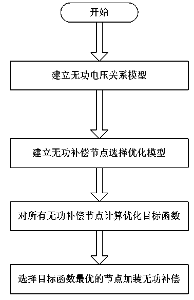
[0042] Such as figure 1 As shown, a reactive power compensation optimization site selection method based on the sensitivity method includes the following steps:

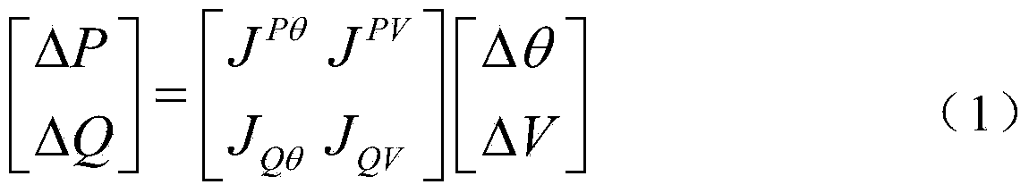
[0043] Step 1. Establishing a reactive power-voltage relationship model;

[0044] Step 2. Select reactive power compensation nodes based on the reactive power voltage relationship model established above, so as to establish an optimization model for reactive power compensation node selection;

[0045] Step 3, calculating the optimization objective function for all reactive power compensation nodes in the reactive power compensation node selection optimization model established above;

[0046] Step 4: Sel...


PUM


Abstract

The invention discloses a sensitivity-based reactive compensation and location optimization method. The method is characterized by comprising the following steps: building a reactive voltage relational model; selecting reactive compensation nodes on the basis of the reactive voltage relational model so as to build a reactive compensation node selection optimization model; calculating optimized objective functions of all the reactive compensation nodes in the built reactive compensation node selection optimization model; selecting to add reactive compensation to the node which obtains the optimal objective function through calculation. Through location optimization of reactive compensation equipment, on the premise of guaranteeing safe and economical operation of a grid, the reception and delivery capabilities of the grid to a new energy are greatly improved, wind curtailment is reduced, and the purpose of improving the on-grid energy of the new energy is achieved.

Description

technical field [0001] The invention relates to the field of site selection of reactive power compensation equipment in reactive power voltage control technology in the process of large-scale new energy power generation, and in particular relates to a reactive power compensation optimal site selection method based on a sensitivity method. Background technique [0002] At present, most of the large-scale new energy bases generated after my country's wind power enters the stage of large-scale development are located in the "three north regions" (Northwest, Northeast, and North China). Large-scale new energy bases are generally far away from the load center, and their power needs to go through long-distance, high-voltage Transported to the load center for consumption. Taking Gansu Power Grid as an example, as of April 2014, the installed capacity of grid-connected wind power in Gansu Power Grid has reached 7.07 million kilowatts, accounting for about 20.2% of the total installed...

Claims


Application Information

Patent Timeline
IPC IPC(8): G06F19/00
Inventor 周强汪宁渤路亮黄华陟晶韩自奋徐陆飞冉亮腾贤亮
Owner STATE GRID CORP OF CHINA
Why Eureka
Try Eureka