Overcurrent electromagnetic release

An electromagnetic release and overcurrent technology, which is applied in the direction of circuits, electrical components, and parts of protective switches, can solve the problems of large volume of releases, expand the application range, reduce operating time, and improve operating efficiency. Effect

Inactive Publication Date: 2015-02-18
PINGGAO GRP +1
View PDF4 Cites 6 Cited by
  • Summary
  • Abstract
  • Description
  • Claims
  • Application Information

AI Technical Summary

Problems solved by technology

[0004] The present invention provides an overcurrent electromagnetic release to solve the technical problem that in the prior art, when the electromagnetic release is applied to large-capacity power equipment, it is necessary to make a relatively large-volume electromagnet, resulting in an excessively large volume of the release.

Method used


Image

  • Overcurrent electromagnetic release
  • Overcurrent electromagnetic release

Examples


Embodiment Construction

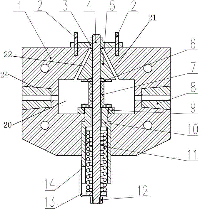
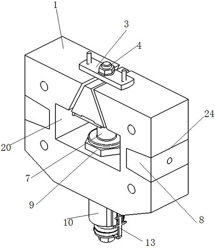
[0026] Such as figure 1 , figure 2 As shown, an embodiment of an overcurrent electromagnetic release, the release in this embodiment includes an annular yoke frame 1, the yoke frame 1 has a circumferential ring wall and a wall surrounded by the circumferential ring wall extending along the front and rear direction The central hole 20 for the system line to pass through, and an upper notch 21 is provided on the inner wall surface of the top ring wall of the yoke frame, and the upper notch 21 extends from the inner wall surface of the top ring wall of the yoke frame 1 to the yoke On the outer wall surface of the ring wall at the top of the iron frame 1, an armature 5 is reciprocatingly moved up and down in the upper gap 21, and the armature 5 moves upward to control tripping and opening when the system line is overcurrent or short-circuited. , the armature 5 is a triangle with a small upper part and a larger lower part, and the upper notch 21 is an angular notch with a smaller...


PUM


Abstract

The invention provides an overcurrent electromagnetic release which comprises a armature, a reset spring and an annular yoke rack. The armature moves upwards to control a corresponding system to release when short circuit currents pass a system circuit. The reset spring drives the armature to move downwards to reset. The yoke rack is provided with a peripheral annular wall and a central hole. The central hole is enclosed by peripheral annular wall, extends along a front-rear direction, and allows the system circuit to penetrate to form an electromagnet. An upper notch is formed in the inner wall surface of the top annular wall of the yoke rack. The armature is assembled into the upper notch in a guide moving manner along an up-down direction. The overcurrent electromagnetic release has the advantages that the yoke rack is added to increase the electromagnetic attractive borne by the armature of the whole release, the application range of the electromagnetic release is expanded, and electromagnetic release miniaturization is benefited.

Description

technical field [0001] The invention relates to an overcurrent electromagnetic release. Background technique [0002] Electromagnetic releases are widely used in medium and low voltage fields due to their simple structure and principle and low cost. The electromagnetic release includes an electromagnet wound by the system line, an armature that drives the circuit breaker mechanism to trip through a transmission mechanism, and a return spring that drives the armature to reset. When the system line passes a normal current, the electromagnetic force generated by the electromagnet is smaller than that of the return spring Given the reaction force provided, the armature cannot be attracted by the electromagnet, and the circuit breaker operates normally. When a short-circuit fault occurs in the system, the short-circuit current exceeds several times the normal current, the electromagnetic force generated by the electromagnet is greater than the reaction force provided by the ...

Claims


Application Information

Patent Timeline
Patent Type & Authority Applications(China)
IPC IPC(8): H01H71/24
CPCH01H71/2409
Inventor 赵芳帅袁端磊朱志豪王海燕李禹生董祥渊
Owner PINGGAO GRP
Why Eureka
Try Eureka