
Conveying groove of combine harvester

A technology for combine harvesters and conveying troughs, applied in the field of conveying troughs, can solve the problems that the conveying troughs do not have the function of preventing grain leakage, and achieve the effects of convenient maintenance, preventing grain leakage at the docking point, and preventing secondary material leakage problems

Inactive Publication Date: 2015-02-25
江苏华源建工集团有限公司
View PDF5 Cites 1 Cited by
  • Summary
  • Abstract
  • Description
  • Claims
  • Application Information

AI Technical Summary

Problems solved by technology

[0003] The technical problem to be solved by the present invention is that the existing conveying trough does not have the function of preventing grain leakage

Method used


Image

  • Conveying groove of combine harvester
  • Conveying groove of combine harvester
  • Conveying groove of combine harvester

Examples


Embodiment Construction

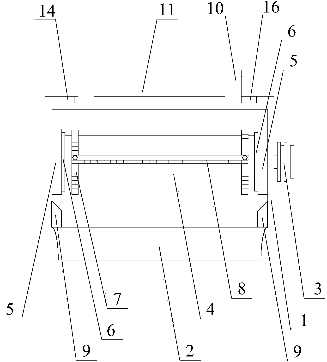
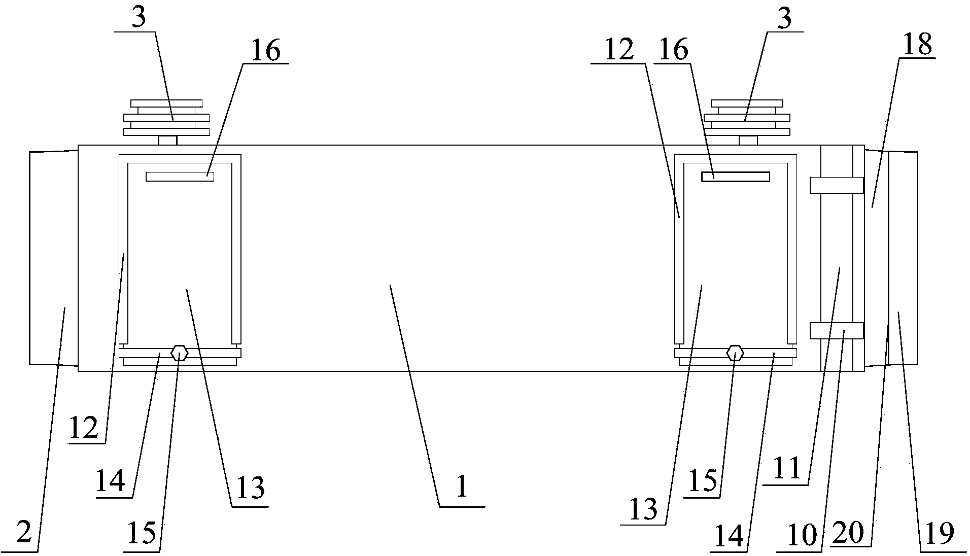
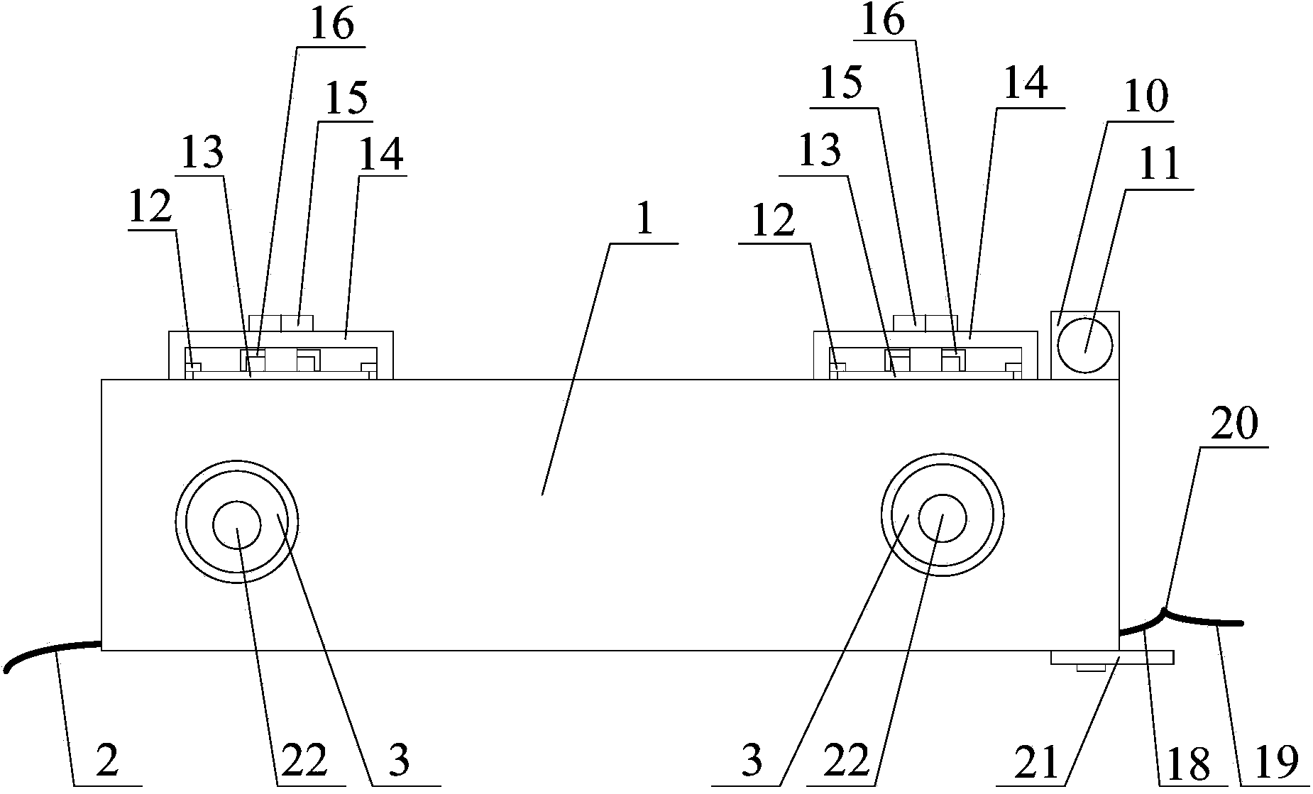
[0018] Such as Figure 1-3 As shown, the delivery trough of the combine harvester of the present invention includes a delivery trough body 1, two rotary drums 4 and two delivery chains 7; A rotating beam 11 is horizontally arranged on the support 10, and the axial direction of the rotating beam 11 is parallel to the upper edge of the grass inlet of the conveying trough body 1; The lower edge of the inner side of the grass outlet of the tank body 1 is provided with a leak-proof arc-shaped plate; the leak-proof arc-shaped plate includes a front arc-shaped plate 19 and a rear arc-shaped plate 18 that are butted together, and the rear arc-shaped plate 18 is fixed on the conveying trough On the inner lower edge of the grass outlet of the body 1, and protrude outward from the grass outlet; an upwardly protruding rib 20 is formed at the joint of the front arc plate 19 and the rear arc plate 18; The lower edge of the inner side of the grass mouth is provided with an outwardly protrud...


PUM

PropertyMeasurementUnit
Hem lengthaaaaaaaaaa

Abstract

The invention provides a conveying groove of a combine harvester. The conveying groove comprises a conveying groove body, two rotary rollers and two conveying chains. A rubber pad is arranged on the outer side of the lower edge of a straw outlet of the conveying groove body, and a leakage preventing arc-shaped plate is arranged at the lower edge of the inner side of the straw outlet of the conveying groove body; an upwards-protruding protruding edge is formed at the portion where a front arc-shaped plate body is in butt joint with a back arc-shaped plate body; an outwards-extending straw inlet arc-shaped plate is arranged at the lower edge of the inner side of a straw inlet of the conveying groove body; the two rotary rollers are installed in the straw inlet and the straw outlet of the conveying groove body in a rotary mode, the two conveying chains surround the two rotary rollers, and conveying tooth rakes are arranged on the two conveying chains at equal intervals; clearing windows are arranged at the top of the conveying groove body, notches are formed in the edges of the three sides of each clearing window, and a cover plate with which the corresponding clearing window is covered is inserted into the corresponding notch. By means of the conveying groove, leakage can be effectively prevented when the conveying groove is in butt joint with a header and a threshing machine, and the good application prospects are achieved.

Description

technical field [0001] The invention relates to a conveying trough, in particular to a conveying trough of a combine harvester. Background technique [0002] At present, when the trough of the existing combine harvester is transporting forage, grain leakage problems often occur at the joints with the header and the joint with the threshing machine. Once the grain leakage problem occurs, it will definitely cause economic losses. In order to avoid grain loss, the existing chute must be improved. Contents of the invention [0003] The technical problem to be solved by the invention is that the existing conveying trough does not have the function of preventing grain leakage. [0004] In order to solve the above technical problems, the present invention provides a conveying trough for a combine harvester, which includes a conveying trough body, two rotary drums and two conveying chains; A rotating beam is arranged horizontally on the seat, and the axial direction of the rotat...

Claims


Application Information

Patent Timeline
IPC IPC(8): A01D41/12A01F12/46
Inventor 赵卫青朱凤年
Owner 江苏华源建工集团有限公司
Learn More