Workpiece pressing mechanism

A technology of pressing mechanism and workpiece, applied in metal processing machinery parts, clamping devices, manufacturing tools, etc., can solve the problems of small torque and insufficient clamping of workpieces.

Inactive Publication Date: 2015-02-25
重庆川茂建材有限公司
View PDF0 Cites 5 Cited by
  • Summary
  • Abstract
  • Description
  • Claims
  • Application Information

AI Technical Summary

Problems solved by technology

However, in the clamping device with the above structure, the torque of the gear rotation is small, so the force exerted by the gear on the rack is small, and there may be a problem of insufficient clamping when clamping the workpiece.

Method used


Image

  • Workpiece pressing mechanism

Examples


Embodiment Construction

[0012] The present invention will be described in further detail below by means of specific embodiments:

[0013] The reference signs in the drawings of the specification include: .

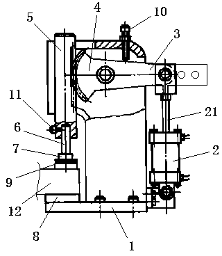
[0014] like figure 1 As shown, the workpiece pressing mechanism includes a machine base 1 and a rack 5, wherein a bevel gear 4 with a booster handle 3, a swing cylinder 2 and a pressing head 7 with a connecting rod 6 are also provided. On the machine base 1 There is a chute, the rack 5 is located in the chute, the center of the bevel gear 4 is connected to the base 1 in rotation, and the bevel gear 4 is meshed with the rack 5, and the piston rod 21 of the swing cylinder 2 is hinged with the booster handle 3, as figure 1 As shown, the booster handle 3 is provided with a plurality of hinged holes, so that different hinged holes can be selected to change the torque. The end of the swing cylinder 2 away from the piston rod 21 is swingably connected with the base 1, and the base 1 is connected to the...


PUM


Abstract

The invention discloses a workpiece pressing mechanism which comprises a machine base and a rack and is further provided with a conical gear with a strength increasing handle, an oscillating air cylinder and a pressing head with a connection rod. The machine base is provided with a sliding groove, and the rack is located in the sliding groove. The circle center position of the conical gear is connected with the machine base in a rotating mode, and the conical gear is meshed with the rack. A piston rod of the oscillating air cylinder is hinged to the strength increasing handle. The end, away from the piston rod, of the oscillating air cylinder is connected with the machine base in an oscillating mode. The position, opposite to one end of the rack, of the machine base is provided with a supporting base. The connection rod of the pressing head is connected with the end, close to the supporting base, of the rack. The workpiece pressing mechanism is large in clamping force, and workpieces can be stably clamped.

Description

technical field [0001] The invention relates to a clamping device, in particular to a workpiece pressing mechanism. Background technique [0002] In machine tool processing, it is usually necessary to use a clamping mechanism to fix the workpiece before subsequent processing, so the clamping mechanism is widely used in the field of workpiece processing. [0003] The clamping device usually includes a power source and a clamping mechanism. The existing gear-coordinated rack clamping device usually uses a motor as the power source. The motor drives the gear to rotate, and the gear drives the rack to move, thereby realizing clamping and clamping. The act of releasing a workpiece. However, in the clamping device with the above structure, the rotational moment of the gear is small, so the force exerted by the gear on the rack is relatively small, and the problem of loose clamping may occur when clamping the workpiece. Contents of the invention [0004] In view of the above-me...

Claims


Application Information

Patent Timeline
Patent Type & Authority Applications(China)
IPC IPC(8): B23Q3/08
CPCB23Q3/08B23Q2703/04
Inventor 陈其钧
Owner 重庆川茂建材有限公司
Why Eureka
Try Eureka