Pipe end marking device of automatic pipe cutter

A technology of marking device and pipe cutting machine, which is applied in metal processing and other directions, can solve problems such as poor effect and low marking efficiency, and achieve the effect of obvious effect, stable workpiece quality and uniform imprint.

Inactive Publication Date: 2015-02-25
STABILUS JIANGSU
View PDF7 Cites 0 Cited by
  • Summary
  • Abstract
  • Description
  • Claims
  • Application Information

AI Technical Summary

Problems solved by technology

[0003] In order to overcome the shortcomings of the existing automatic pipe cutting machine, such as low marking efficiency, poor effect, and potential safety hazards, the present invention provides a pipe end marking device for automatic pipe cutting machines

Method used


Image

  • Pipe end marking device of automatic pipe cutter

Examples


Embodiment Construction

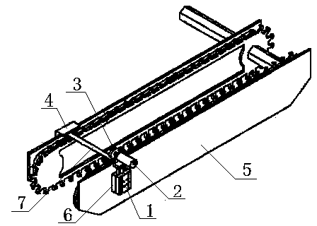
[0013] like figure 1 It is a structural schematic diagram of the present invention, a pipe end marking device for an automatic pipe cutting machine, including a cylinder 1, a motor 2, a brush 3, a baffle 4 and a base guide rail 6, and the baffle 4 and the base guide rail 6 are installed on the automatic pipe cutting machine respectively. On both sides of the motor transmission chain 5, the cylinder 1 is slidably connected on the base guide rail 6, fixed by bolts, the motor 2 is installed on the cylinder 1, and the hairbrush 3 is installed on the motor 2. The motor 2 is connected to the piston rod at the top of the cylinder 1. Hairbrush 3 is disc-shaped, is connected on the rotating shaft of motor 2. The baffle plate 4 and the hair brush 3 are symmetrically distributed on both sides of the transmission chain 5 of the automatic pipe cutting machine, and are pressed on the two ends of the pressure pipe 7 respectively. The baffle plate 4 is "L" shaped and blocks the side and upp...


PUM


Abstract

The invention relates to the technical field of automatic pipe cutters, in particular to a pipe end marking device of an automatic pipe cutter. The pipe end marking device comprises an air cylinder, a motor, a brush, a baffle and a base guide rail. The baffle and the base guide rail are installed on the two sides of a transmission chain of the automatic pipe cutter respectively. The air cylinder is connected to the base guide rail in a sliding mode and fixed through a bolt. The motor is installed on the air cylinder, and the brush is installed on the motor. The air cylinder, the motor and the circular brush are installed at the side portion of the transmission chain of the automatic pipe cutter, in the pipe cutting process, the air cylinder automatically presses the end of a pressing pipe, the motor is used for driving the circular brush to rotate, and the end of the pressing pipe is printed with a clear mark. By means of the pipe end marking device, one procedure and one operator are removed, the labor intensity is relieved, the working efficiency is greatly improved, marks are uniform, the definition degree effect is obvious, and great convenience is brought to subsequent grooving and pipe packing, the workpiece quality is stable, and the yield is greatly increased.

Description

technical field [0001] The invention relates to the technical field of automatic pipe cutting machines, in particular to a pipe end marking device for automatic pipe cutting machines. Background technique [0002] Existing automatic pipe cutting machines cannot make brush marks on one end of the pipe during the pipe cutting process, and can only manually brush marks on one end of the pipe on the drilling machine after the pipe cutting is completed. Adopting this method has the following disadvantages: 1. One more process and one operator are added, 2. The production efficiency is low, 3. The pipe end marks are not clear, 4. There are certain potential safety hazards. Contents of the invention [0003] In order to overcome the problems of low marking efficiency, poor effect and potential safety hazards in the existing automatic pipe cutting machine, the present invention provides a pipe end marking device for an automatic pipe cutting machine. [0004] The technical soluti...

Claims


Application Information

Patent Timeline
Patent Type & Authority Applications(China)
IPC IPC(8): B26D7/27
Inventor 眭伟峰田学峰
Owner STABILUS JIANGSU
Why Eureka
Try Eureka