Supercharge Your Innovation With Domain-Expert AI Agents!

Anchoring method of carbon-fiber composite inhaul cable

A technology of composite materials and anchoring methods, which is applied to bridge parts, erection/assembly of bridges, bridges, etc., can solve problems such as differences in modulus and friction properties, fracture of reinforcement, and uneven stress on reinforcement in the cross-section of the anchorage , to achieve the effect of uniform performance, stress peak relief and high strength

Active Publication Date: 2015-02-25
FASTEN HONGSHENG GRP CO LTD
View PDF6 Cites 9 Cited by
  • Summary
  • Abstract
  • Description
  • Claims
  • Application Information

AI Technical Summary

Problems solved by technology

[0004] One: The horizontal anchoring causes the precipitation direction of the aggregate in the anchor filler to be perpendicular to the axis of the anchor, resulting in differences in the modulus and friction properties of the filler in the cross-section of the anchor. When the cable is axially loaded, the anchor transverse Uneven stress on the reinforcement in the cross-section
[0005] Second: Horizontal anchoring causes the anchor filler in the anchor to be in close contact with the front and rear end wire baffles of the anchor. When the cable is axially loaded, the front end of the anchor will hinder the forward advancement of the anchor filler, thereby Stress concentration occurs at the loaded end of the anchor, so the static load failure form of the carbon fiber composite cable produced by the horizontal anchoring often shows that the tendon breaks at the anchored end, and the tensile strength of the carbon fiber composite cannot be fully utilized.

Method used


Image

  • Anchoring method of carbon-fiber composite inhaul cable

Examples


Embodiment Construction

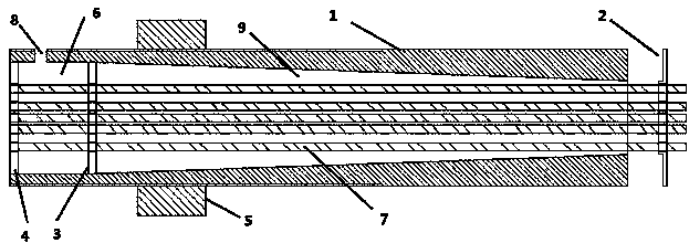
[0025] See figure 1 The present invention relates to a method for anchoring a carbon fiber composite cable. First, the carbon fiber composite ribs 7 at both ends of the carbon fiber composite cable are set in the anchors at both ends, and then horizontal grouting is performed in the anchor at one end Perform vertical grouting again, and then perform horizontal grouting first and then vertical grouting in the anchor at the other end.

[0026] The structure of the anchorage is as follows. The anchorage includes a steel sleeve 1, a front end of the anchorage, a first branching plate 3 at the back end of the anchor, and a second branching plate 4 at the back end of the anchor. The outer surface of the anchorage has Thread, a nut 5 is sleeved on the thread on the outer surface of the anchor, and a first cavity 6 is present in the steel sleeve 1 between the first wire dividing plate 3 at the rear end of the anchor and the second wire dividing plate 4 at the rear end of the anchor The ...


PUM


Abstract

The invention relates to an anchoring method of a carbon-fiber composite inhaul cable. The anchoring method is characterized by comprising the steps of arranging carbon-fiber composite ribs at the two ends of the carbon-fiber composite inhaul cable into anchoring devices at the two ends, carrying out horizontal grounding and then vertical grouting on the anchoring device at one end, and carrying out horizontal grounding and then vertical grouting on the anchoring device at the other end. By means of the anchoring method of the carbon-fiber composite inhaul cable, the deposition direction of aggregate in anchoring packing is the same as the axial direction of the anchoring devices, anchoring packing in the cross sections of the anchoring devices is uniform in performance, the gradient change direction of the modulus of the anchoring packing is the same as the axial direction of the anchoring devices, the modulus of the anchoring packing is gradually increased from the front ends to the rear ends of the anchoring devices, the peak stress of the ribs inside the anchoring devices can be relieved easily, meanwhile, the situation that because stress concentration of the carbon-fiber composite ribs is generated at the load bearing ends of the anchoring devices, the carbon-fiber composite ribs fracture too early can be avoided, and accordingly the high strength of the carbon-fiber composite ribs can be brought into full play.

Description

Technical field [0001] The invention relates to a method for anchoring a carbon fiber composite cable, which is mainly used for anchoring a carbon fiber composite cable. Background technique [0002] Carbon fiber composite material has excellent properties such as light weight, high strength, no rust, corrosion resistance, fatigue resistance, low thermal expansion coefficient, and good shock absorption performance. The carbon fiber composite material bar is used for the cable components in the long-span cable bridge. Fundamentally solve the problem of poor fatigue and corrosion resistance of steel cables. At present, the anchoring method of the domestic carbon fiber composite cable is horizontal grouting, that is, the anchor is placed horizontally, the carbon fiber composite bar passes through the split hole baffle at the front and rear ends of the anchoring, and the anchoring filler is poured in from the middle opening of the anchor. There are vent holes at the front and rear e...

Claims


Application Information

Patent Timeline
Patent Type & Authority Applications(China)
IPC IPC(8): E01D21/00E01D19/14
CPCE01D19/14E01D21/00
Inventor 朱元林刘礼华张继文
Owner FASTEN HONGSHENG GRP CO LTD
Features
  • R&D
  • Intellectual Property
  • Life Sciences
  • Materials
  • Tech Scout
  • Unparalleled Data Quality
  • Higher Quality Content
  • 60% Fewer Hallucinations
Learn More