Parallel-connection liquid-electricity feed suspension system

A suspension system, parallel technology, applied in the field of vehicle suspension system, can solve problems such as unfavorable vehicle ride comfort control, difficulty in realizing separate adjustment, etc., to improve handling stability and driving comfort, stabilize generator speed, cost reduction effect

Active Publication Date: 2015-02-25
WUHAN UNIV OF TECH +1
View PDF9 Cites 25 Cited by
  • Summary
  • Abstract
  • Description
  • Claims
  • Application Information

AI Technical Summary

Problems solved by technology

[0003] The currently disclosed hydraulic-electric energy-feeding shock absorber (ZL 2010 2 0117853.0) is a closed system consisting of a hydraulic actuator and a set of hydraulic rectifying valves, in which the hydraulic check bridge structure is formed by the compression stroke and extension. Both can recover energy, but the damping force of the compression stroke of the shock absorber is greater than that of the extension stroke, and it is difficult to achieve separate adjustments, which is not conducive to the ride comfort control of the vehicle

Method used


Image

  • Parallel-connection liquid-electricity feed suspension system
  • Parallel-connection liquid-electricity feed suspension system
  • Parallel-connection liquid-electricity feed suspension system

Examples


Embodiment 1

[0026] Embodiment 1. A parallel hydraulic-electric energy-feeding suspension system

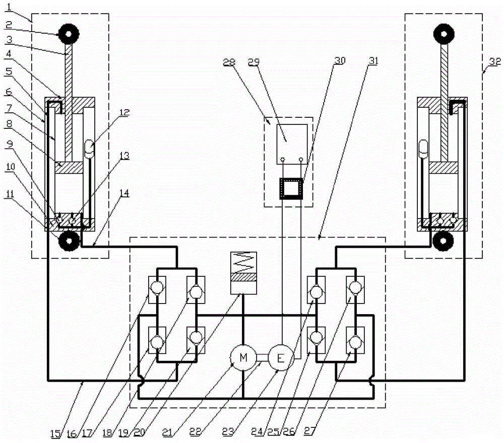
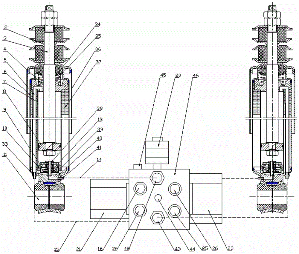
[0027] The parallel hydraulic electric energy feed suspension system provided by this embodiment 1 is a kind of suspension system such as figure 1 and figure 2 The structure shown is composed of two hydraulic cylinder modules with the characteristics of two-way cylindrical shock absorbers connected in parallel to a hydraulic-electric energy conversion module with the characteristics of a complete rectifier bridge. The external oil pipe 14 of the rod cavity is matched and connected.

[0028] The first hydraulic cylinder module 1 is transformed from a two-way cylinder shock absorber. The hydraulic cylinder module consists of a piston push rod hinge 2, a piston push rod 3, a guide 4, an extension stroke pipeline 5, Oil storage cylinder 6, working cylinder 7, piston 8, compensation valve 9, compression valve seat 10, cylinder body hinge 11, compression valve 13, oil pipe flange with rod cavity...

Embodiment 2

[0031] Embodiment 2. The second parallel hydraulic electric energy feed suspension system

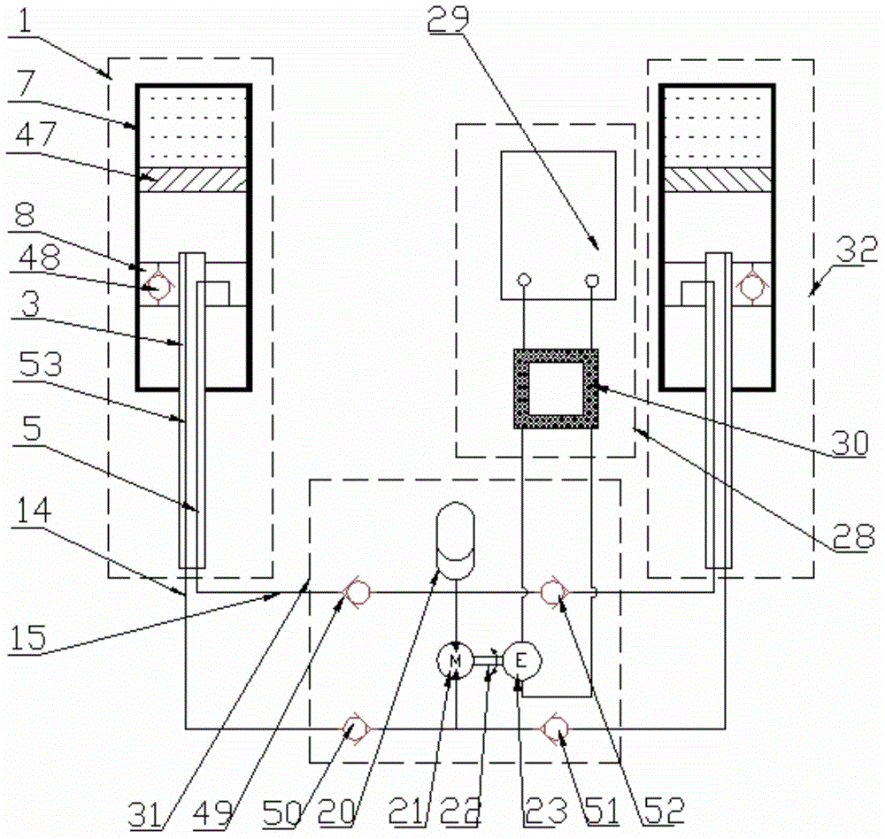
[0032] The parallel hydraulic electric energy feed suspension system provided by this embodiment 2 is a kind of suspension system such as image 3 and Figure 4 The shown structure consists of two hydraulic cylinder modules with the characteristics of a single-tube oil-pneumatic shock absorber connected in parallel to a hydraulic-electric energy conversion module with the characteristics of a partial rectifier bridge. The two modules are externally connected to the oil pipe 15 and The external oil pipe 14 of the rodless cavity is matched and connected.

[0033] The first hydraulic cylinder module 1 is transformed from a single-tube oil-gas shock absorber. The hydraulic cylinder module consists of a piston push rod 3, an extension stroke pipeline 5, a working cylinder 7, a piston 8, a floating piston 47. The piston compression valve 48 is composed of a compression stroke pipeline 53, w...


PUM


Abstract

The invention relates to a parallel-connection liquid-electricity feed suspension system. The system is composed of a plurality of hydraulic actuation cylinder modules (1), a liquid-electricity energy conversion module (31) and a control and energy storage module (28), wherein the hydraulic actuation cylinder modules are in parallel connection with the liquid-electricity energy conversion module (31) and the control and energy storage module (28), and each hydraulic actuation cylinder module is matched with an elastic element to form a suspension sub system used for being connected with a wheel and a frame. Vibration energy caused by bumpiness of a road surface can be partly converted into electricity, and damping force needed by the system and used for attenuating vibration is supplied by reverse electrodynamic force generated when a power generator works. Accordingly, the suspension system can be actively or semi-actively controlled by controlling the work condition of the power generator. Meanwhile, damping force of the suspension sub systems of a vehicle can be transmitted by means of hydraulic pipelines, dynamic control of the posture of a vehicle body can be achieved by being matched with corresponding control strategies, and accordingly operation stability and driving comfort of the vehicle are better.

Description

technical field [0001] The invention relates to a vehicle suspension system, in particular to a hydraulic-electric energy-feeding suspension system in which a plurality of hydraulic-electric energy-feeding shock absorbers are connected in parallel. Background technique [0002] When the vehicle is running on the road, the relative movement between the sprung mass and the unsprung mass of the vehicle will occur due to the unevenness of the road surface, the acceleration and deceleration of the vehicle, and the steering and other operations. This part of the excitation energy is converted into heat energy and dissipated into the atmosphere, thereby quickly attenuating the vibration of the vehicle. If these energies can be partially recovered and utilized, the energy consumption of the vehicle can be reduced, thereby achieving the purpose of saving energy. The present invention is just based on such an idea, that is, replacing the traditional shock absorber with a shock absorb...

Claims


Application Information

Patent Timeline
Patent Type & Authority Applications(China)
IPC IPC(8): F16F9/28F16F9/32F16F9/50
CPCB60G13/14F16F9/28F15B21/08F16F9/32F16F9/50
Inventor 徐琳过学迅方志刚周泉许煊煚资小林张杰张晗龚边杨波
Owner WUHAN UNIV OF TECH
Why Eureka
Try Eureka