Magnetic field structure for magnetic induction gear encoder

An encoder and magnetic induction technology, applied in the field of encoders, can solve the problems of uncompact structure, measurement error, splashing and hurting people, etc.

Inactive Publication Date: 2015-02-25
深圳市富士鸿泰科技有限公司
View PDF5 Cites 7 Cited by
  • Summary
  • Abstract
  • Description
  • Claims
  • Application Information

AI Technical Summary

Problems solved by technology

[0005] The method that takes at present is that sensor 12 is positioned between permanent magnetic field 11 and gear 13, as Figure 5 and Image 6 As shown, this method can distinguish module 0.4 with the highest accuracy, and can effectively subdivide module 0.4 to 100, that is, 100 times frequency output, but the smaller recognition distance has not been broken through. If module 0.3 is achieved, because it is Using the strong magnetic method, the strong magnetism is easy to attract some ferromagnetic powde

Method used


Image

  • Magnetic field structure for magnetic induction gear encoder
  • Magnetic field structure for magnetic induction gear encoder
  • Magnetic field structure for magnetic induction gear encoder

Examples


Embodiment Construction

[0029] In order to make the object, technical solution and advantages of the present invention clearer, the present invention will be further described in detail below in conjunction with the accompanying drawings and embodiments. It should be understood that the specific embodiments described here are only used to explain the present invention, not to limit the present invention.

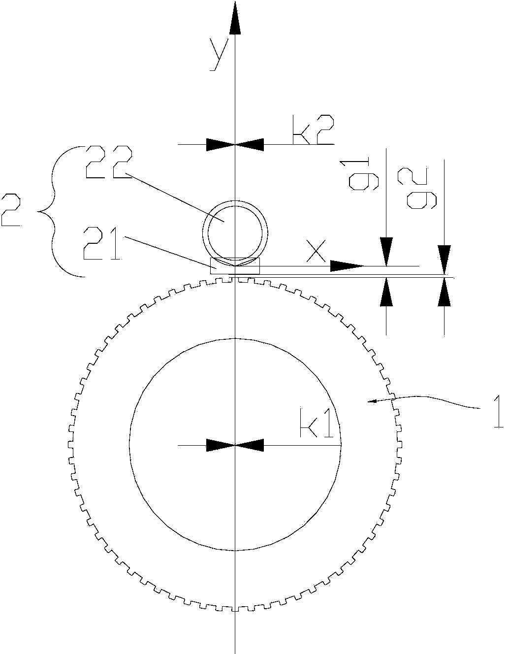
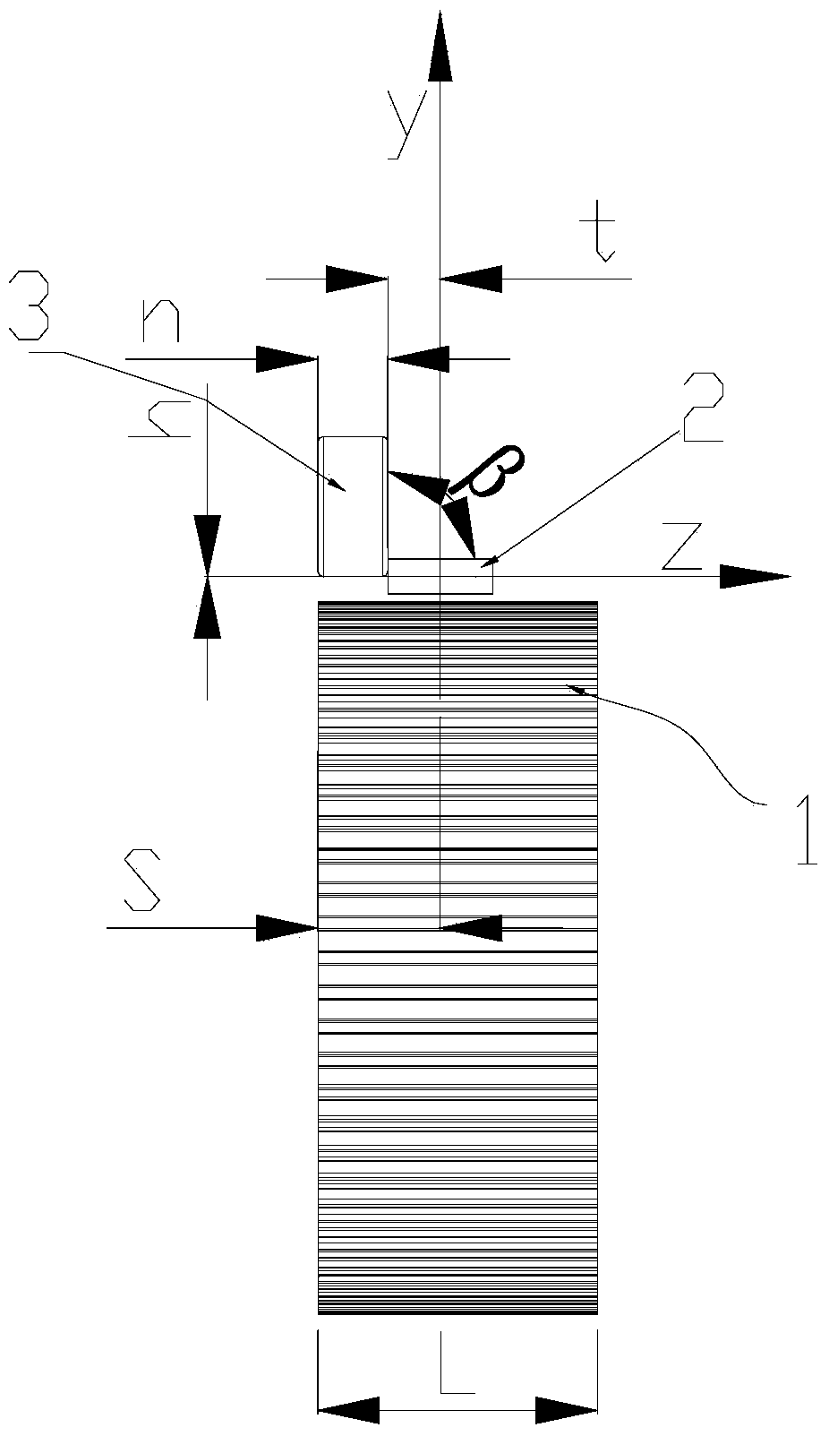
[0030] see figure 1 and figure 2 , figure 1 It is a front view of a magnetic field structure for a magnetic induction gear encoder of the present invention, figure 2 It is a left view of a magnetic field structure for a magnetic induction gear encoder of the present invention; in this embodiment, a magnetic field structure 10 for a magnetic induction gear encoder includes a gear encoding disc 1 and an induction head 2, and a sensor is housed in the induction head 2 21 and permanent magnet 22, the sensor 21 is located directly above the tooth top of the gear coding disc 1, the permanent magnet ...


PUM

PropertyMeasurementUnit
Surface magnetic field strengthaaaaaaaaaa
Diameteraaaaaaaaaa
Thicknessaaaaaaaaaa

Abstract

The invention discloses a magnetic field structure for a magnetic induction gear encoder. The magnetic field structure comprises a gear encoding disc and an inductive head, a sensor and a permanent magnet are installed in the inductive head, the sensor is located right above the tooth top of the gear encoding disc, the axial deviation between the permanent magnet and the center line y of the sensor inside the inductive head is t, the t is smaller than or equal to 5 mm, the radial deviation between the side, with the edge close to the sensor, of the permanent magnet and the center line z of the sensor is h, the h is larger than or equal to -3 mm and smaller than or equal to 3 mm, a skewing angle formed between the end face of the permanent magnet and the xy plane is alpha, the alpha is larger than or equal to -38 degrees and smaller than or equal to 38 degrees, a skewing angle formed between the end face of the permanent magnet and the xz plane is beta, and the beta is larger than or equal to -36 degrees and smaller than or equal to 36 degrees. By means of the magnetic field structure for the magnetic induction gear encoder, the encoder sensitivity is higher, the accuracy can reach the level that the module0.3 can be accurately distinguished, and the tooth distance capable of being distinguished is smaller than or equal to 0.94 mm; compared with an encoder with the same resolution ratio, the size is smaller, the structure is more compact, the externally-expressed magnetism is weaker, scrap iron is not prone to being absorbed, and a scrap iron protection device is avoided.

Description

technical field [0001] The invention relates to the technical field of encoders, in particular to a magnetic field structure for a magnetic induction gear encoder. Background technique [0002] The magnetic ring encoder in the prior art is composed of an induction head and a magnetic ring encoder disk, and the magnetic ring encoder disk is processed by injection molding, die-casting or casting by ferromagnetic material powder and plastic material as a binder. Formed, and then the outer ring is evenly magnetized into small magnetic moments connected in series by magnetization, such as image 3 Shown, and with a certain mechanical package to install on the measured shaft, such as Figure 4 shown. When the motor with a magnetic ring encoder disk makes a circular motion, when each small magnetic moment rotates from far to near and approaches the induction, different magnetic field strengths and gradients will be generated. The built-in magnetic sensor of the induction head will...

Claims


Application Information

Patent Timeline
IPC IPC(8): G01D5/14G01D5/16
Inventor 陆丕清
Owner 深圳市富士鸿泰科技有限公司
Why Eureka
Try Eureka