
A device for predicting and displaying rigid body collision trajectory

A trajectory prediction and rigid body technology, applied in special data processing applications, instruments, electrical digital data processing, etc., can solve the problem of no real-time visual display of motion trajectories

Active Publication Date: 2018-05-01
SUZHOU INST OF BIOMEDICAL ENG & TECH CHINESE ACADEMY OF SCI
View PDF6 Cites 2 Cited by
  • Summary
  • Abstract
  • Description
  • Claims
  • Application Information

AI Technical Summary

Problems solved by technology

[0005] At present, in the field of collision trajectory prediction, there is no real-time visual display of the motion trajectory. The inventor hopes to use wearable observation equipment and simple cameras to design a system that can predict the collision trajectory in advance and give users an intuitive display effect. Equipment, which can be used for the training of planar collision sports such as gateball and billiards, as well as the field of human-computer interaction related to collision prediction

Method used


Image

  • A device for predicting and displaying rigid body collision trajectory
  • A device for predicting and displaying rigid body collision trajectory
  • A device for predicting and displaying rigid body collision trajectory

Examples


Embodiment Construction

[0030] The advantages and spirit of the present invention can be further understood through the following detailed description of the invention and the accompanying drawings.

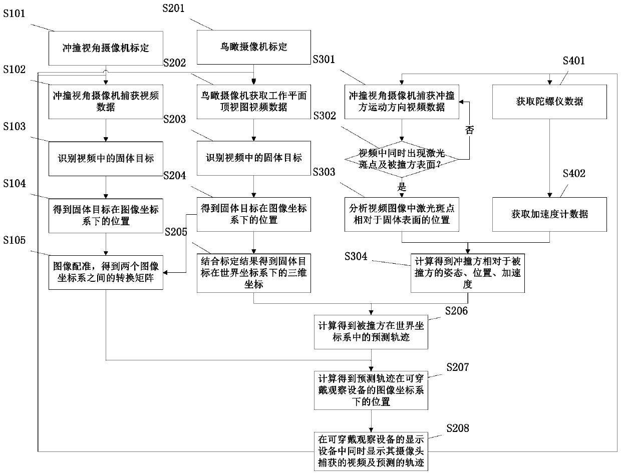
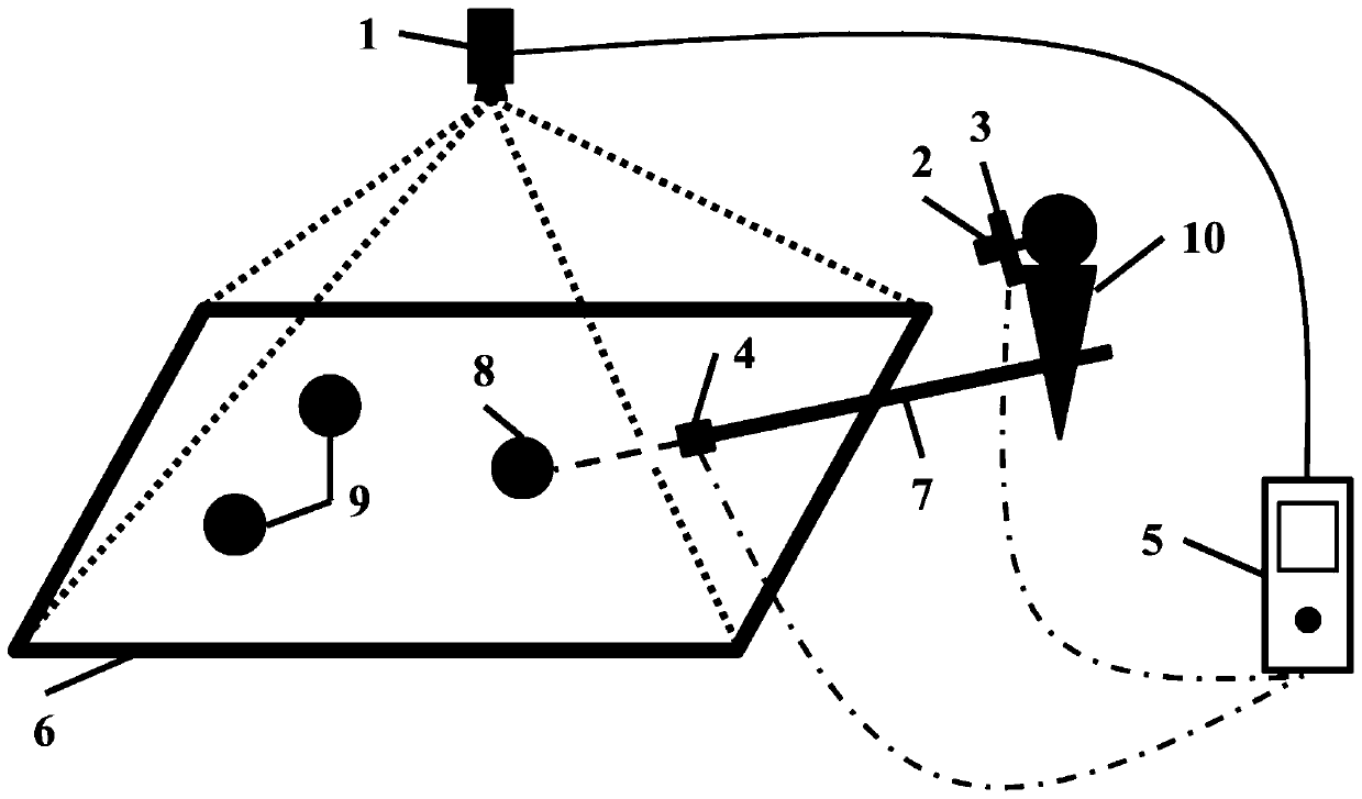
[0031] Attached figure 1 For the work flow chart, attached figure 2 It is a schematic diagram of a preferred example, where the composition of the preferred example is a bird's-eye view camera 1, a collision view camera 2, a wearable observation device 3, a sighting adapter 4, a data processing device 5, a working plane 6, a colliding party 7, a collided party 8, and others Rigid body 9, user 10.

[0032] In this preferred example, the collision view camera 2 and the wearable observation device 3 are placed on the same hardware structure and worn by the user 10.

[0033] In this preferred example, the bird's-eye view camera 1 and the data processing device 5 are connected through a physical cable for data communication, and the collision view camera 2, the wearable observation device 3, the aiming adapter 4 a...


PUM


Abstract

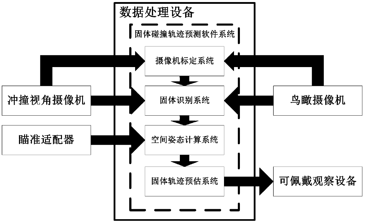
The invention provides a rigid-body collision track prediction display unit. The rigid-body collision track prediction display unit is composed of an aerial camera, a collision view angle camera, a wearable observation device, an aiming adapter, data processing equipment and a rigid-body collision track prediction software system. The rigid-body collision track prediction software system is configured in the data processing equipment, and is divided into a camera calibration system, an object identification system, a spatial posture calculating system and a rigid-body track estimation system. The spatial positions of rigid bodies on the working plane and the posture and force of the colliding party are obtained by analyzing video data transmitted by the aerial camera and the collision view angle camera by combination with spatial pose information transmitted by the aiming adapter, so that possible movement tracks generated after the colliding party and the collided party collide are obtained through calculation, and the tracks and actual scenes are overlapped to be displayed on a display screen of the wearable observation device. The collision tracks can be predicted and displayed in real time, and users can adjust the positions and movement states of the rigid bodies before collision happens.

Description

Technical field [0001] The invention relates to a rigid body collision trajectory prediction display device, in particular to a rigid body collision trajectory prediction display device including a bird's-eye view camera, a collision perspective camera, a wearable observation device, an aiming adapter, a data processing device, and a rigid body collision trajectory prediction software system. It is suitable for the prediction and real-time display of rigid body collisions, such as the sports training of flat collision balls such as billiards and gateballs, and related human-computer interaction fields. Background technique [0002] Wearable observation equipment is a miniature electronic device that can be worn on the body to go out and perform activities. It has a head-mounted display, a communication module, and has certain data processing capabilities. At present, most wearable observation equipment is in the form of glasses or helmets. And all adopt lightweight design, so tha...

Claims


Application Information

Patent Timeline
Patent Type & Authority Patents(China)
IPC IPC(8): G06F17/50
Inventor 耿辰戴亚康郑健郁朋
Owner SUZHOU INST OF BIOMEDICAL ENG & TECH CHINESE ACADEMY OF SCI
Learn More