Insulation puncture cable connecting device

A connecting device and insulation piercing technology, applied in the direction of needle tip/slotted plate contact and conductive connection used for connecting and penetrating insulated wire/cable core wire, can solve the problems of low installation efficiency, inconvenient operation, etc. Simple on-site construction and improved installation efficiency

Inactive Publication Date: 2015-02-25
JIANGSU JIAMENG ELECTRICAL EQUIP
View PDF3 Cites 4 Cited by
  • Summary
  • Abstract
  • Description
  • Claims
  • Application Information

AI Technical Summary

Problems solved by technology

[0004] The technical problem solved by the present invention is to overcome the defects of inconvenient operation and low instal

Method used


Image

  • Insulation puncture cable connecting device

Examples


Embodiment Construction

[0023] The present invention is further illustrated below by means of examples, but the present invention is not limited to the scope of the examples.

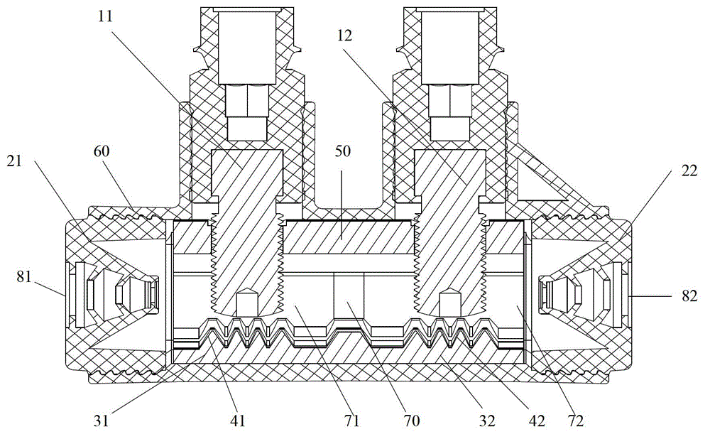
[0024] figure 1 It is a cross-sectional view of an insulation piercing cable connection device in a preferred embodiment of the present invention, such as figure 1 As shown, the insulation piercing cable connection device involved in this embodiment includes: torque bolt 11, torque bolt 12, cable receiving part 50, tapered pier array 41, tapered pier array 42, anvil 31 and anvil 32;

[0025] Wherein, the cable accommodating part 50 is used for accommodating the cables to be connected; the torque bolts 11 and the torque bolts 12 are used to provide thrust for the cables extending into the cable accommodating part 50; the anvil 31 and the anvil 32 are placed in the cable accommodating part 50, used to clamp the cable together with the torque bolt 11 and the torque bolt 12 respectively in the direction of thrust;

[0026] The t...


PUM


Abstract

The invention discloses an insulation puncture cable connecting device which comprises a pressure application portion, a cable containing portion, at least one penetrating portion and at least one anvil portion. The cable containing portion is used for containing a cable to be connected. The pressure application portion is used for providing push force for the cable. The anvil portions are arranged in the cable containing portion and used for clamping the cable together with the pressure application portion in the direction of the push force. The penetrating portions are arranged on the anvil portions and/or the pressure application portion and used for penetrating through an insulation layer of the cable. Containing ducts are formed, torque bolt are pushed to penetrate through the insulation layer of the cable in an extruded mode, site construction is easier and more convenient, and mounting efficiency is improved.

Description

technical field [0001] The invention relates to a connection device, in particular to an insulation piercing cable connection device. Background technique [0002] In the prior art, butt joints are often required in the line connection process of overhead lines. At present, two methods are mainly used: butt joints of splicing pipes, that is, peeling off the outer sheath of the cables during installation, and then crimping them with a crimping tool, and then Then take insulation protection measures; butt joint of pre-insulated aluminum tubes, that is, peel off the outer sheath of the cable during installation, and then crimp it with a crimping tool. [0003] Because the above two methods require a lot of tools and operation steps, they bring a lot of operational inconvenience to the on-site construction, resulting in low installation efficiency. Contents of the invention [0004] The technical problem solved by the invention is to overcome the defects of inconvenient opera...

Claims


Application Information

Patent Timeline
IPC IPC(8): H01R43/00H01R4/24
CPCH01R43/00H01R4/2404
Inventor 施希锋徐华锋
Owner JIANGSU JIAMENG ELECTRICAL EQUIP
Why Eureka
Try Eureka