Simply supported hollow plate girder bending resistance reinforcement method

A technology of hollow slabs and main girders, applied in bridge reinforcement, bridges, bridge maintenance, etc., can solve the problems of lagging stress and strain, limited improvement of the bending bearing capacity of main girders, and failure to reach the design value of tensile strength, so as to improve the utilization rate , Improve the effect of bending bearing capacity

Active Publication Date: 2015-08-05
广州展亚土木工程技术有限公司
View PDF5 Cites 2 Cited by
  • Summary
  • Abstract
  • Description
  • Claims
  • Application Information

AI Technical Summary

Problems solved by technology

The commonly used reinforcement method is to directly paste steel plates on the bottom plate of the main beam for reinforcement. The disadvantage of this reinforcement form is that the steel plates cannot participate in bearing the constant load bending moment that has acted on the main beam before reinforcement, but can only participate in bearing the vehicle load and After adding the internal force caused by the dead load, the flexural bearing capacity of the main girder is limited
Compared with the existing tensile reinforcement of the main girder, the stress and strain of the steel plate are relatively lagging behind. In the limit state, the stress and strain are far below the design value of the tensile strength, but the tensile reinforcement of the main girder has reached its tensile design value. strength, thus causing the steel plate to fail to give full play to its material properties

Method used


Image

  • Simply supported hollow plate girder bending resistance reinforcement method
  • Simply supported hollow plate girder bending resistance reinforcement method
  • Simply supported hollow plate girder bending resistance reinforcement method

Examples


Embodiment Construction

[0047] The present invention will be further described below in conjunction with drawings and embodiments.

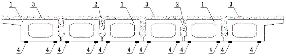
[0048] This embodiment is for figure 1 The hollow slab girder bridge consisting of six girders 1 is shown to be reinforced. The length, width and height of the main girder 1 of the bridge are (12960╳990╳700)mm, there are joints 2 for pouring concrete between the main girders, and the concrete bridge deck cast-in-place layer 3 is above the main girders. Before reinforcement, there is water seepage and whitening in the hinge joints of the hollow slab, and some hinge joints have cracking and falling off phenomena. There are many transverse cracks near the mid-span of multiple main girders. It is necessary to strengthen the main girder against bending and recast the hinge joints. .

[0049] Before the construction, determine whether the bridge possesses two conditions for adopting the reinforcement method of the present invention by following calculations:

[0050] A. Th...


PUM


Abstract

A simply supported hollow plate girder bending resistance reinforcement method has the construction steps of demounting ancillary facilities of a bridge deck, chiseling hinge joints between girders and a bridge deck cast-in-situ layer, and retaining the girders; setting up operation platforms used for construction to carry out surface treatment on the girders; jacking the girders through jacks under the precondition that safety of the girders is guaranteed; removing mid-span bending moments of dead load of the girders; sticking steel plates after the bending moments of dead load of the girders are removed; pouring concrete to the hinge joints and the bridge deck cast-in-situ layer; synchronously uninstalling the jacks after the curing time is reached, so that the girders are located on supports, and then removing the jacks; pouring concrete to the hinge joints and the bridge deck cast-in-situ layer; restoring the ancillary facilities of the bridge deck, and completing the bending resistance reinforcement of the girders. The simply supported hollow plate girder bending resistance reinforcement method has the beneficial effects that the steel plates are stuck after the mid-span bending moments of dead load of the girders are removed, thus the steel plates can not only participate in the bearing of the load of automobiles and later-imposed dead load, but also participate in the bearing of the removed bending moments of dead load, so that the bending resistance bearing capacity of the girders can be improved; the steel plates are stuck when the strain stress of rebars at mid-span tensile regions of the girders is decreased, so that the material performance of the reinforcing steel plates can be fully exerted better.

Description

technical field [0001] The invention relates to highway bridges, in particular to a bending-resistant reinforcement method for existing simply supported hollow slab girders. Background technique [0002] Hollow slab girder bridge is one of the most commonly used structural forms of small-span bridges of 10-20m. Most of them are simply supported beams, which are suitable for factory mass production and prefabricated construction. The section of the hollow slab girder bridge is composed of multiple main girders, and hinge joints are set between the main girders. The pouring layer forms a whole and bears loads such as cars. In the longitudinal direction of the bridge, the main girder is the most important stressed member. [0003] However, after the hollow slab girder bridge is put into operation, transverse cracks often appear in the bottom plate of the main girder. The main manifestations are: they occur near the mid-span floor of the main girder, with a minimum spacing of ...

Claims


Application Information

Patent Timeline
IPC IPC(8): E01D22/00
CPCE01D22/00
Inventor 薛兴伟万亮
Owner 广州展亚土木工程技术有限公司
Why Eureka
Try Eureka