Eureka AIR delivers breakthrough ideas for toughest innovation challenges, trusted by R&D personnel around the world.

Steel reinforced concrete combination pillar with built-in bunched spiral stirrups and manufacturing method

A technology of stirrup-shaped steel and spiral stirrups, which is applied to the field of built-in and bundled spiral stirrup-shaped steel-concrete composite columns and the production field, can solve the problems of limited cross-sectional form and poor restraint effect of the spiral stirrups, and can solve the problems of reducing bearing capacity, The construction is convenient and fast, and the effect of cross-section form and size is convenient

Inactive Publication Date: 2016-04-13
GUANGXI UNIV
View PDF6 Cites 8 Cited by
  • Summary
  • Abstract
  • Description
  • Claims
  • Application Information

AI Technical Summary

Problems solved by technology

[0006] The technical problem to be solved by the present invention is to provide a steel-concrete composite column with built-in and bundled spiral stirrups with high bearing capacity, good ductility, good seismic performance and convenient construction, so as to overcome the constraint effect of spiral stirrups in the existing spiral stirrup concrete column technology Inadequacies such as poor and limited cross-sectional forms

Method used


Image

  • Steel reinforced concrete combination pillar with built-in bunched spiral stirrups and manufacturing method
  • Steel reinforced concrete combination pillar with built-in bunched spiral stirrups and manufacturing method
  • Steel reinforced concrete combination pillar with built-in bunched spiral stirrups and manufacturing method

Examples


Embodiment 1

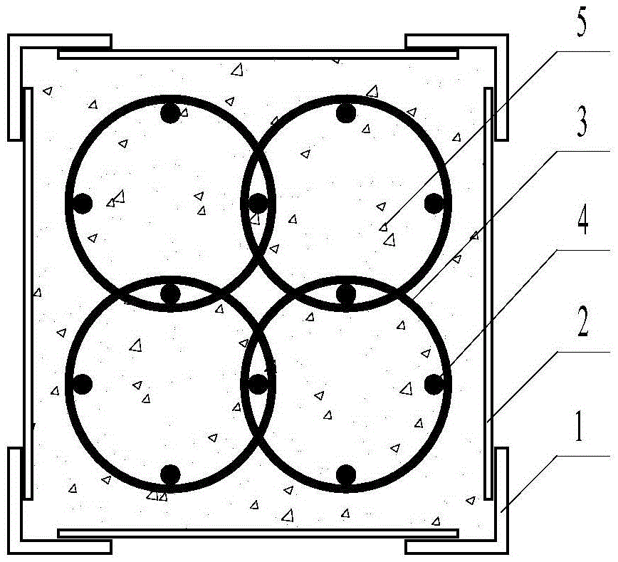
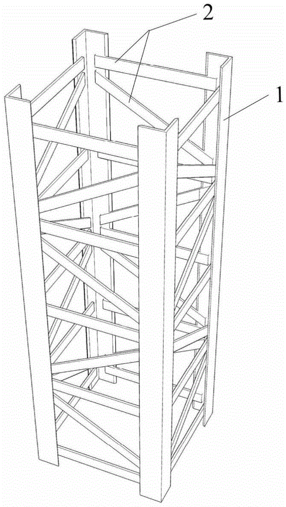
[0033] Such as figure 1 , image 3 with Figure 4 As shown, the steel-concrete composite column with built-in bundled spiral stirrups includes the angle steel 1 of embodiment 1, steel embellishments 2, spiral stirrups 3, longitudinal steel bars 4, and concrete 5. Spiral stirrups 3 and longitudinal steel bars 4 are bound to form a reinforcement cage, which is wrapped in concrete 5, and the concrete 5 is wrapped with a steel truss; The distance from the outer edge of the outermost spiral stirrup to the inner edge of the steel trim is 30mm-50mm, which facilitates the installation of reinforcement cages and steel trusses, as well as the pouring of concrete.

[0034] The cross-section of the steel-concrete composite column with built-in bundled spiral stirrups in this embodiment is a square, and the angle steel is an equilateral angle steel, which is arranged at the four corners of the column. Four spiral stirrups 3 are arranged in the column, and the four spiral stirrups are in ...

Embodiment 2

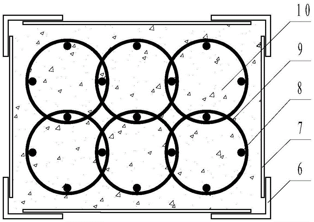
[0042] The technical solution of this embodiment is basically the same as that of Embodiment 1, the difference is that its structure is as figure 2 , Figure 5 with Image 6 As shown, the section of the steel-concrete composite column with built-in bundled spiral stirrups is rectangular, and 6 spiral stirrups 9 are arranged in the column, and the 6 spiral stirrups are arranged side by side in a rectangular shape, which can improve the compression-bending mechanical properties of the composite column. Angle steel 6 is unequal angle steel, which is set at the four corners of the composite column. The long leg of the angle steel is located on the long side of the composite column section, and the short leg of the angle steel is located on the short side of the composite column section, so as to improve the bending resistance of the composite column. Mechanical properties and shock resistance. This embodiment 2 also has the steel embellishment 7, the longitudinal reinforcement ...


PUM


Abstract

The invention discloses a steel reinforced concrete combination pillar with built-in bunched spiral stirrups. The combination pillar comprises angle steel, steel lacing and batten elements, the spiral stirrups, longitudinal reinforcing steel bars and concrete. The section of the combination pillar is in a square or rectangular shape. The spiral stirrups are arranged side by side and bundled with the longitudinal reinforcing steel bars to form a reinforcement cage. The reinforcement cage is wrapped with the concrete. The concrete is wrapped with a section steel truss. The section steel truss is formed by welding the angle steel and the steel lacing and batten elements. Due to the fact that the concrete is wrapped with the section steel, the problem that the concrete is cracked and peeled off early, and therefore the bearing capacity is lowered is effectively solved. The spiral stirrups arranged side by side produce a restriction effect on the concrete inside therein, and the problem that the spiral stirrup concrete pillar is weak in restriction ability under the bending effect is solved. The flexural rigidity, flexural capacity and anti-seismic property of the combination pillar are effectively improved through the section steel truss. Reinforcing steel bars in a frame node area middle beam can penetrate through the section of the pillar, and construction is convenient and fast. The steel reinforced concrete combination pillar is particularly applicable to a structural pillar with the high requirement for anti-seismic property or a heavy-load pillar bearing large vertical loads.

Description

technical field [0001] The invention relates to a building structure component, in particular to a steel-concrete composite column with built-in bundled spiral stirrups and a manufacturing method thereof. Background technique [0002] Due to the confinement effect of the spiral stirrup on the concrete, the core concrete of the spiral stirrup concrete column is in a three-dimensional compression state when it is under pressure, and has good bearing capacity and ductility. At the same time, due to the configuration of continuous transverse reinforcement, it has excellent seismic resistance. Performance and energy dissipation capacity, are widely used in various structures. However, the structural column still has some unavoidable shortcomings, which limit its application in engineering structures with higher seismic requirements and larger vertical loads; for example: [0003] 1. Since the concrete column with spiral stirrups has a concrete protective layer, the protective la...

Claims


Application Information

Patent Timeline
Patent Type & Authority Applications(China)
IPC IPC(8): E04C3/34
CPCE04C3/34
Inventor 陈宗平周春恒经承贵谭秋虹陈德钊
Owner GUANGXI UNIV
Why Eureka
Eureka Blog
Learn More