Gas discharge tube with trigger electrodes

A gas discharge tube and trigger electrode technology, which is applied to spark gaps, electrical components, and circuits with auxiliary triggering devices, can solve the problems of prolonged response time and large freewheeling current, and achieve shortened response time, stable performance, and flow through. The effect of large capacity

Inactive Publication Date: 2015-02-25
NANJING UNIV OF INFORMATION SCI & TECH
View PDF7 Cites 4 Cited by
  • Summary
  • Abstract
  • Description
  • Claims
  • Application Information

AI Technical Summary

Problems solved by technology

[0004] In order to solve the technical problems raised by the above-mentioned background technology, the present invention aims to provide a gas discharge tube with a trigger electrode, which solves the problems of prolonged response time and large freewheeling of the existing gas discharge tube, and improves the lightning protection effect

Method used


Image

  • Gas discharge tube with trigger electrodes
  • Gas discharge tube with trigger electrodes
  • Gas discharge tube with trigger electrodes

Examples


Embodiment Construction

[0019] The technical solutions of the present invention will be described in detail below in conjunction with the accompanying drawings.

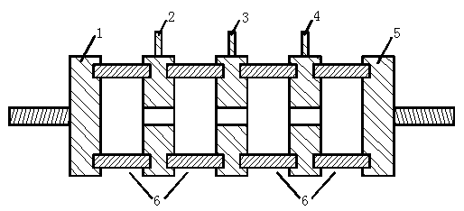
[0020] Such as figure 1 The structure schematic diagram of the present invention is shown, a gas discharge tube with trigger electrodes, including 2 main discharge electrodes 1 and 5, 3 trigger electrodes 2, 3, 4 and 4 ceramic tubes 6. The two main discharge electrodes are arranged at both ends of the gas discharge tube, and the three trigger electrodes are arranged in sequence between the two main discharge electrodes, and between adjacent electrodes (the electrodes here refer to the main discharge electrodes and the trigger electrodes) They are connected by ceramic tubes filled with inert gas argon.

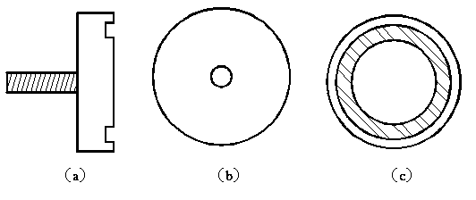
[0021] Such as figure 2 The schematic diagram of the structure of the main discharge electrode in the present invention is shown, including (a), (b), (c) 3 figures, respectively the front view, left view and right view of the main dischar...


PUM


Abstract

The invention discloses a gas discharge tube with trigger electrodes. The gas discharge tube comprises two main discharge electrodes, the n trigger electrodes and n+1 ceramic tubes, wherein n is larger than or equal to one, the two main discharge electrodes are arranged at the two ends of the gas discharge tube, the n trigger electrodes are sequentially arranged between the two main discharge electrodes, every two adjacent electrodes are connected through the corresponding ceramic tube, and the ceramic tubes are filled with inert gas. By means of the gas discharge tube, the problems of the long response delay and the large follow current of an existing gas discharge tube are solved, and the lightning protection effect is improved.

Description

technical field [0001] The invention belongs to the technical field of lightning protection, and in particular relates to a gas discharge tube with a trigger electrode. Background technique [0002] The gas discharge tube is a gap type lightning protection component, which has been widely used in the lightning protection of the communication system. The gas discharge tube plays the role of discharging lightning transient overcurrent and limiting overvoltage. Due to the large insulation resistance between the electrodes of the discharge tube, under the distributed capacitance, it has obvious advantages in lightning protection for high frequency and microwave signals. The working principle of the discharge tube is gas discharge. When a certain voltage is applied between the electrodes, an uneven electric field will be generated between the electrodes, and the gas between the electrodes will start to dissociate under the action of the electric field. When the dielectric stren...

Claims


Application Information

Patent Timeline
Patent Type & Authority Applications(China)
IPC IPC(8): H01T4/16H01T4/20H01T2/02
Inventor 李祥超陈则煌陈璞阳周中山
Owner NANJING UNIV OF INFORMATION SCI & TECH
Why Eureka
Try Eureka