Photovoltaic charger control device and method

A photovoltaic charger and control device technology, applied in circuit devices, battery circuit devices, current collectors, etc., can solve problems such as maintenance, inability to guarantee battery voltage, and inability to guarantee battery voltage maintenance, so as to avoid stuck situations and track effects. Good and efficient use

Inactive Publication Date: 2015-02-25
XIAMEN KECAN INFORMATION TECH
View PDF3 Cites 12 Cited by
  • Summary
  • Abstract
  • Description
  • Claims
  • Application Information

AI Technical Summary

Problems solved by technology

[0004] Generally, solar charging devices use BUCK step-down circuit, that is, the photovoltaic voltage is higher than the battery voltage to charge. Generally, there are constant current charging control methods and constant voltage charging control methods. Constant current charging is the maximum power charging. When the battery voltage has not yet reached a certain When the voltage value (set as Vm), it has been charged with the maximum power of solar energy, an approximate constant current charging, because the energy of solar energy is not constant, affected by weather changes, the energy change will still be large, constant voltage charging That is, when the battery voltage reaches Vm, in order to prevent overcharging, the battery voltage is not allowed to continue to rise, and the battery voltage is maintained at Vm for charging. At this time, if the solar energy is sufficient or the load does not increase, photovoltaic energy can maintain the battery voltage at Vm. For charging, the photovoltaic voltage at this time will not be at the maximum power point. If the photovoltaic energy suddenly decreases or the load suddenly increases after switching to constant voltage control, the photovoltaic energy cannot guarantee that the battery voltage is maintained at Vm, which is a common practice in the industry. Yes, when the battery voltage drops to a certain value, recharge at maximum power, but before recharging at maximum power, there will be a problem, because photovoltaic energy cannot guarantee that the battery voltage is at Vm, and the solar charging device will always keep the BUCK circuit The duty cycle of the switching tube of the power device is adjusted to be large. When the photovoltaic voltage is adjusted to the left side of the P-V curve of the plate, the lower the photovoltaic voltage, the smaller the photovoltaic energy, and the lower the battery voltage, and it is even more difficult to guarantee battery voltage maintenance. At Vm, until the photovoltaic voltage is pulled down to be basically the same as the battery voltage, that is, the duty cycle of the switch tube of the power device is adjusted to the maximum, and it is in a stuck state until the driver is turned off again and restarts the next maximum power charging from the photovoltaic open circuit voltage point.

Method used


Image

  • Photovoltaic charger control device and method
  • Photovoltaic charger control device and method

Examples


Embodiment Construction

[0040] The present invention will be further described below in conjunction with the accompanying drawings and embodiments.

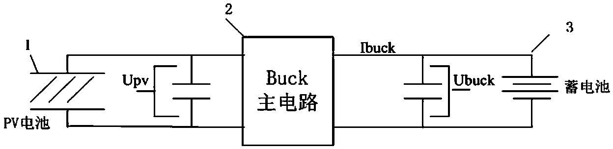
[0041] like figure 2 It is shown that the main topology of the photovoltaic charger in this embodiment is a Buck circuit.

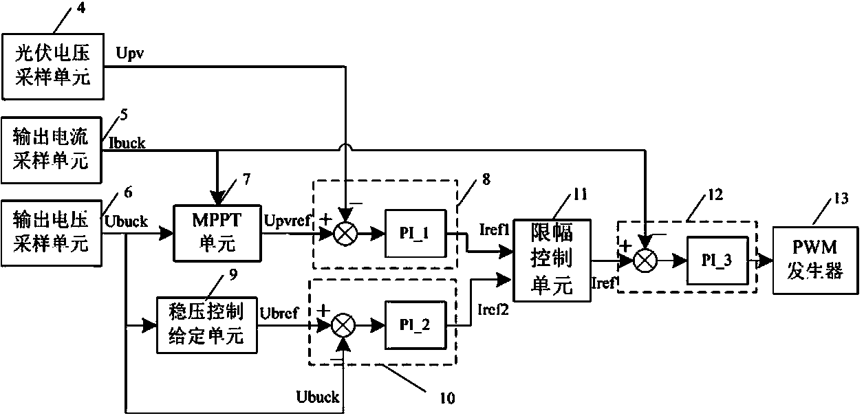
[0042] Please refer to figure 1, the present invention provides a photovoltaic charger control device, which is characterized in that it includes a photovoltaic voltage sampling unit 4 for sampling the output voltage signal Upv of the photovoltaic plate 1;

[0043] An output current sampling unit 5 for sampling the output current signal Ibuck of the photovoltaic charger;

[0044] An output voltage sampling unit 6 for sampling the output voltage signal Ubuck of the photovoltaic charger;

[0045] An MPPT unit 7, according to the output current signal Ibuck and the output voltage signal Ubuck of the photovoltaic charger,

[0046] Use the maximum power tracking technology to perform maximum power tracking on the photovoltaic po...


PUM


Abstract

The invention relates to a photovoltaic charger control device which comprises a photovoltaic voltage sampling unit, an output current sampling unit, an output voltage sampling unit, an MPPT unit, a first voltage controller, a voltage stabilizing control given unit, a second voltage controller, an amplitude limiting control unit, a current controller and a PWM generator. A photovoltaic charger control method comprises the steps that an MPPT control ring, a voltage stabilizing control ring, two voltage inner rings and a current control outer ring are adopted, the MPPT control ring output minimum value and the voltage stabilizing control ring output minimum value are selected as the given Iref of the current control outer ring, the output current value Ibuck of a photovoltaic charger is used as the feedback of the current control outer ring, the current control outer ring outputs the driving duty ratio to the PWM generator, and the PWM generator generates PWM driving signals to drive a switch tube of a main circuit of the photovoltaic charger to work. According to the photovoltaic charger control device and method, it is ensured that the photovoltaic voltage is always on the right side of a polar plate P-V curve, no output current jumping occurs, and it is ensured that photovoltaic energy is used more efficiently.

Description

technical field [0001] The invention relates to a photovoltaic charger control device and a control method. Background technique [0002] With the increasing human demand for energy and the reduction of traditional energy sources, energy issues have become an urgent issue. As a clean and pollution-free energy source, solar energy has become the main direction of modern energy development. [0003] In the solar off-grid power generation system, the solar energy is usually converted into DC power of a certain voltage level by the solar charging device for the use of DC power equipment, and the excess energy is stored in the battery for use when there is a lack of solar energy. The use of solar energy requires maximum power tracking to improve the utilization rate of solar energy. In addition, due to unreasonable charging and discharging of batteries, the proportion of batteries damaged in advance accounts for a large proportion of the total number of damaged batteries, so it ...

Claims


Application Information

Patent Timeline
Patent Type & Authority Applications(China)
IPC IPC(8): H02J7/00
CPCH02J7/00H02J7/0003H02J7/007H02J2207/20
Inventor 崔福军许勇枝张少育曾春保
Owner XIAMEN KECAN INFORMATION TECH
Why Eureka
Try Eureka