Permanent magnet eddy current speed controller based on conjugated magnetic feed rotor

A magnetic rotor and eddy current technology, which is applied in the field of permanent magnet eddy current governors, can solve the problems of a large increase in the length of the extension shaft, a large axial space occupation, and a bulky mechanism, so as to improve safety and reliability. The effect of reducing the axial size and reducing the production cost

Active Publication Date: 2015-02-25
西安巨舟电子设备有限公司
View PDF10 Cites 2 Cited by
  • Summary
  • Abstract
  • Description
  • Claims
  • Application Information

AI Technical Summary

Problems solved by technology

This permanent magnet attraction is an unfavorable factor to the driving machine or load machine. In order to eliminate this magnetic attraction, the adjustment method of the first type of permanent magnet speed governor is set to a pair of permanent disks or a pair of conductor disks to displace in opposite directions, while The axial displacement mechanism of the moving rotor in the opposite direction is relatively complicated. For example, a set of lever hinge mechanisms are evenly distributed along the circumference of the fifth rotor. The number of parts is large, the processing is difficult, and the space occupied in the axial direction is large. The performance of anti-harsh environment is also sharply reduced
Later, on December 23, 2009, the authorized announcement date, the Chinese patent with the authorized announcement number CN201369666Y, improved the above-mentioned lever mechanism to a rack and pinion mechanism, which has indeed made progress, but still has difficulties in guaranteeing machining accuracy, difficulty in installation and anti-pollution ability Inferior defects
Application publication number CN101997396A, the Chinese patent on March 30, 2011, which was published on March 30, 2011, uses a double-headed screw mechanism, which is only suitable for low-power products, and also has defects such as difficult installation and poor anti-pollution ability, and if used For common products with slightly higher power, its mechanism will be quite heavy, which will bring additional load to the isolation bearing, and the strength of the disk needs to be reinforced, and even the normal operation of the product cannot be realized under the action of huge axial magnetic force
[0007] The above-mentioned second type of permanent magnet governor has bigger defects latent, and its defects are reflected in the fact that the factors that generate additional vibration are difficult to eliminate when applying high power or high speed
[0008] In addition, the above-mentioned permanent magnet governor also has deficiencies in the design of the structure. For example, its adjustment mechanism is composed of two sets of angular bearings, which are adjusted by means of a cam mechanism, which results in a large increase in the length of the extension shaft, resulting in a more complicated structure of the product. , bulky, the driver of the adjustment mechanism is set on the side of the product, which requires a rather long push-pull rod and occupies a large area
Based on the above, the inventor disclosed a self-feeding permanent magnet eddy current governor in the publication number 103915972A, published on July 09, 2014, but found in practice that according to the product described in the patent application As an overload protection type, it is an available product, but its applicable speed regulation range is relatively small, so the scope of application is limited

Method used


Image

  • Permanent magnet eddy current speed controller based on conjugated magnetic feed rotor
  • Permanent magnet eddy current speed controller based on conjugated magnetic feed rotor
  • Permanent magnet eddy current speed controller based on conjugated magnetic feed rotor

Examples


Embodiment Construction

[0032] The present invention will be described in further detail below in conjunction with the accompanying drawings.

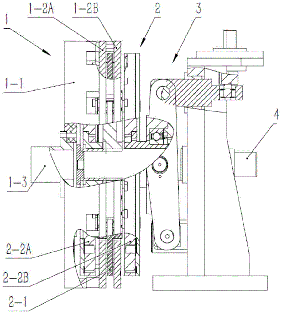
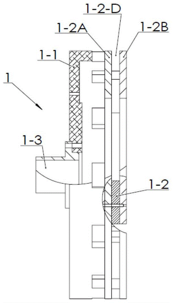
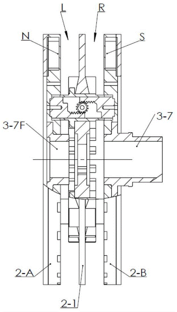
[0033] see Figures 1 to 7D As shown, a permanent magnet governor based on a conjugate-fed rotor in the present invention includes: a coaxially arranged secondary shaft (not shown) and an extended main shaft 4; the extended main shaft 4 is provided with a permanent magnet rotor 2, and the permanent The magnetic rotor 2 includes a pair of permanent magnetic disks A 2-2A and permanent magnetic disks B 2-2B arranged in parallel on the extended main shaft 4, and a conjugate feeder is arranged in parallel between the permanent magnetic disks A 2-2A and permanent magnetic disks B 2-2B. The magnetic rotor 2-1, the conjugate magnetic feed rotor 2-1 is fixedly installed on the extension main shaft 4; the permanent magnetic disk A 2-2A and the permanent magnetic disk B 2-2B are provided with permanent The magnet group; the permanent disk A 2-2A and the permanent disk ...


PUM


Abstract

The invention discloses a permanent magnet eddy current speed controller based on a conjugated magnetic feed rotor. The permanent magnet eddy current speed controller comprises an auxiliary shaft and an extension main shaft, the auxiliary shaft and the extension main shaft are coaxially arranged, the extension main shaft is provided with a permanent magnet plate A, the conjugated magnetic feed rotor and a permanent magnet plate B in parallel, the auxiliary shaft is fixedly provided with a conductor rotor base plate, a conductor plate A and a conductor plate B are fixed to the conductor rotor base plate in parallel, the conductor plates are located between the conjugated magnetic feed rotor and the permanent magnet plates, and the permanent magnet plate A and the permanent magnet plate B are connected with a displacement regulating mechanism which drives the permanent magnet plate A and the permanent magnet plate B to move along the extension main shaft axially and synchronously in opposite directions. A more ingenious topological method is adopted and combined with a feasible optimized electromagnetic and mechanical structure, so that the permanent magnet speed controller based on the conjugated magnetic feed rotor is formed. Two magnetic fields with strength capable of being simply adjusted are formed only on the permanent magnet rotor, and no destructive magnetic acting force exists between the permanent magnet rotor and a conductor rotor which make no contact with each other.

Description

【Technical field】 [0001] The invention belongs to the technical field of mechanical transmission, in particular to a permanent magnet eddy current governor based on a conjugate-fed magnet rotor. 【Background technique】 [0002] The basic principle of the existing permanent magnetic coupling device is to use the relative motion between the conductor rotor and the permanent magnet rotor to induce a vortex magnetic field on the conductor rotor. . Using this mechanism, the power is transmitted from the power side to the load side in a non-contact manner. Its theoretical basis is classic and well-known, and the methods or prototypes for principle verification are diverse and simple, but there are still few mature engineering applications. [0003] The first type of permanent magnet governor is disc-shaped, which adjusts the distance between the conductor rotor and the permanent magnet rotor, that is, adjusts the size of the air gap. The larger the air gap, the smaller the transm...

Claims


Application Information

Patent Timeline
Patent Type & Authority Applications(China)
IPC IPC(8): H02K51/00
Inventor 马小安
Owner 西安巨舟电子设备有限公司
Why Eureka
Try Eureka