Permanent magnet brushless motor sensorless starting method

A permanent magnet brushless motor and sensor technology, applied in motor control, electronic commutation motor control, electrical components, etc., can solve the problems of start-up failure, large amount of calculation, and high requirements for control chip calculation performance, and achieve fast start-up speed, Wide range of applications and the effect of improving the success rate of startup

Inactive Publication Date: 2015-02-25
张前
View PDF4 Cites 18 Cited by
  • Summary
  • Abstract
  • Description
  • Claims
  • Application Information

AI Technical Summary

Problems solved by technology

In addition, since the motor is not completely static at the initial position, but vibrates slightly at the pre-positioned position, the initial state cannot be completely consistent every time it is started, which is an unavoidable interference to the switching time, so the pre-positioned start method is also There is a possibility of startup failure, and its calculation load is relatively large, which requires relatively high calculation performance of the control chip
[0006] The optimization process of the above three commonly used start-up methods is complicated, and the start-up program needs to be modified correspondingly every time the load changes, which is poor in versatility, and there is an inevitable possibility of start-up failure. Applications in the field of control

Method used


Image

  • Permanent magnet brushless motor sensorless starting method
  • Permanent magnet brushless motor sensorless starting method
  • Permanent magnet brushless motor sensorless starting method

Examples


Embodiment Construction

[0029] In order to make the technical means, creative features, goals and effects achieved by the present invention easy to understand, the present invention is further described by taking a two-pole motor as an example, combined with specific diagrams.

[0030] The first step of the present invention is rotor pre-positioning:

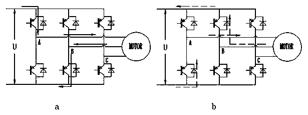
[0031] According to the two-by-two energization method, the rotor is to be positioned at figure 1 (a) The position shown in (a) needs to conduct the A-C phase (A-C means that the current flows from the A phase to the C phase), but if the rotor happens to be at the figure 1 In the position shown in (b), turning on phase A-C cannot make the rotor locate at figure 1 (a) shows the location, in order to prevent figure 1 (b) When the situation shown in (b) occurs, the pre-positioning stage adopts the method of turning on phase A-B first and then turning on phase A-C. The time for turning on phase A-B can be shorter, as long as the rotor is moving, the time...


PUM


Abstract

The invention discloses a permanent magnet brushless motor sensorless starting method. The permanent magnet brushless motor sensorless starting method comprises the steps that firstly, a rotor is positioned at a specific position through a rotor prepositioning device, single-step acceleration is carried out according to the given single-step acceleration current and single-step acceleration time obtained by calculation, single-step acceleration is directly switched to closed loop acceleration after being carried out, rotor position signals in a three-phase suspended state are detected every fixed period, the power-on phase sequence is determined according to the rotor position signals, whether counter potential signals are stable or not is judged through a signal comparison method while closed loop acceleration is carried out, and when stable counter potential signals can be detected within one phase conversion period, a normal counter potential method is switched to for operation, wherein the single-step acceleration and the signal comparison method can ensure that a motor is started at the highest speed, and the closed loop acceleration process can ensure that the motor supplies power accurately in the acceleration start process and step-out is avoided. By means of the method, an efficient permanent magnet brushless motor can be started accurately, rapidly and efficiently, the optimization process is simple, universality is high, the success rate of starting can be improved greatly, no sensitivity to load changes exists, and the start program does not need to be changed when loads and the working station change within a certain range.

Description

technical field [0001] The invention is applicable to the control field of high-speed permanent magnet brushless motors, and in particular relates to a position sensorless starting method for high-speed permanent magnet brushless motors. technical background [0002] At present, the common position sensorless control methods of square wave driven permanent magnet brushless motor mainly include back EMF method, freewheeling diode method, flux linkage function method, current injection method and state observer method. Among them, the back EMF method is widely used in actual development, and it is also a relatively practical position sensorless control method at present. Since the winding back electromotive force of the permanent magnet brushless motor is proportional to the motor speed, there is no back electromotive force before starting, and the back electromotive force is very small at low speed running, so it is difficult to accurately extract the back electromotive force...

Claims


Application Information

Patent Timeline
Patent Type & Authority Applications(China)
IPC IPC(8): H02P6/20
CPCH02P6/181H02P6/20H02P2203/11
Inventor 张前
Owner 张前
Why Eureka
Try Eureka