
Clock signal outputting method and circuit

A clock signal output and circuit technology, applied in the direction of electrical components, automatic power control, etc., can solve the problems of increasing the cost of peripheral circuits, complex circuit design and high clock frequency systems, and achieve the effect of reducing EMI interference

Active Publication Date: 2015-02-25
LONTIUM SEMICON CORP
View PDF4 Cites 6 Cited by
  • Summary
  • Abstract
  • Description
  • Claims
  • Application Information

AI Technical Summary

Problems solved by technology

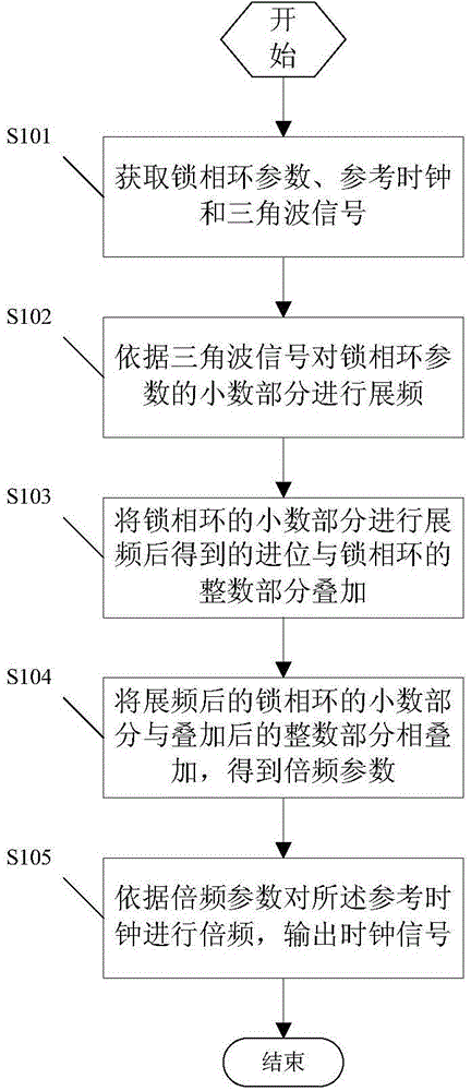
[0004] In view of this, the present application provides a clock signal output method and circuit, which are used to solve the cost of increasing the peripheral circuit caused when the traditional technical solution in the prior art is used to solve the EMI problem, which makes the circuit design complicated and does not solve it from the source The high clock frequency in the high-speed digital system leads to the problem of EMI in the system. This application discloses a clock signal output method and circuit

Method used


Image

  • Clock signal outputting method and circuit
  • Clock signal outputting method and circuit
  • Clock signal outputting method and circuit

Examples


Embodiment Construction

[0042] Aiming at increasing the cost of peripheral circuits caused by adopting traditional technical solutions in the prior art to solve EMI problems, making the circuit design complicated and not solving the problem of EMI in the system caused by the high clock frequency in the high-speed digital system from the source, this application A clock signal output method and circuit are disclosed.

[0043] The following will clearly and completely describe the technical solutions in the embodiments of the application with reference to the drawings in the embodiments of the application. Apparently, the described embodiments are only some of the embodiments of the application, not all of them. Based on the embodiments in this application, all other embodiments obtained by persons of ordinary skill in the art without creative efforts fall within the protection scope of this application.

[0044] figure 1 It is a flow chart of a clock signal output method disclosed in the embodiment o...


PUM


Abstract

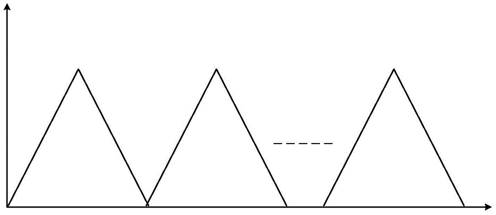
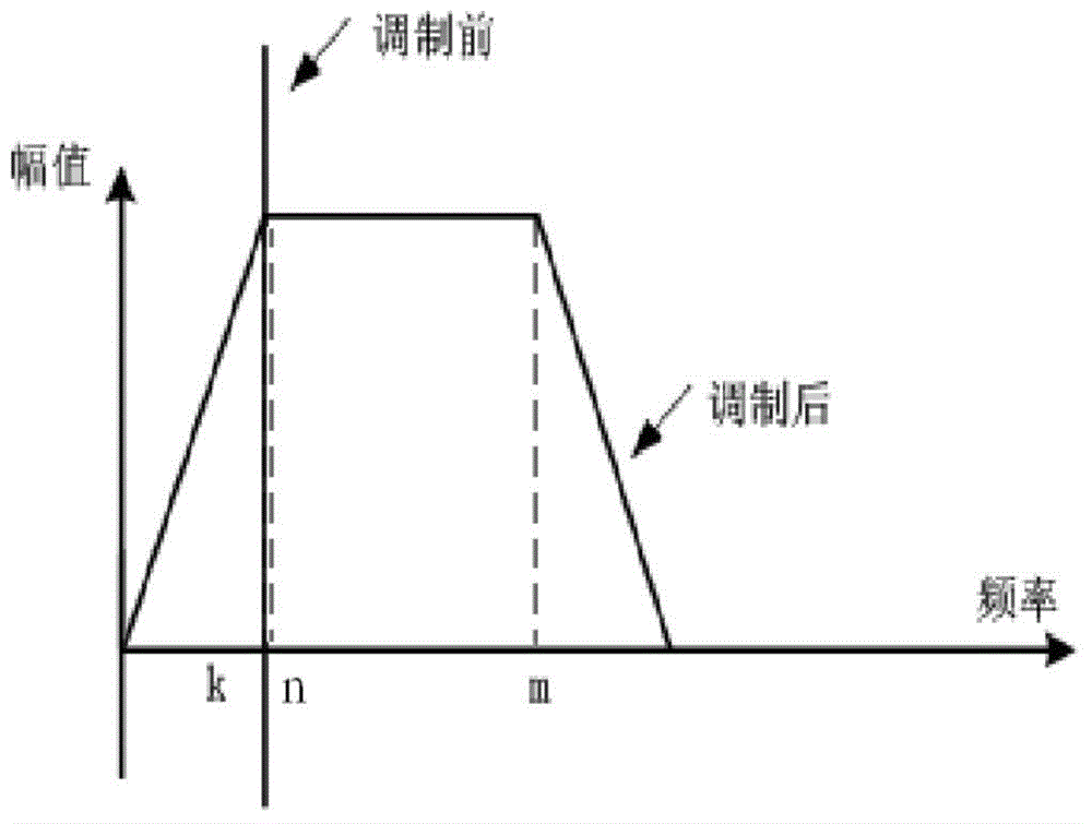
The invention discloses a clock signal outputting method. The method includes subjecting a fractional part of a phase-locked loop parameter to spectrum spreading according to a triangular wave signal; superposing carry obtained by subjecting the fractional part of the phase-locked loop to spectrum spreading and an integral part of the phase-locked loop; superposing the fractional part, subjected to spectrum spreading, of the phase-locked loop and the integral part, subjected to superposition, of the phase-locked loop to obtain a doubled frequency parameter; according to the doubled frequency parameter, subjecting a reference clock to frequency doubling to output a clock signal. According to the method, the fractional part of the phase-locked loop parameter is subjected to spectrum spreading through the triangular wave signal, the fractional part of the phase-locked loop parameter subjected to spectrum spreading is not a fixed value but a triangularly linearly changing value, and thus, energy output of the output clock signal is not under the single frequency but evenly distributed to a small frequency range; energy value of each frequency is low, and EMI (electromagnetic interference) is reduced.

Description

technical field [0001] The present application relates to the technical field of chip anti-jamming processing, and more specifically, to a clock signal output method and circuit. Background technique [0002] Electromagnetic Interference (EMI) is a kind of energy that can affect the performance of electrical / electronic equipment by causing unexpected responses or complete work failures, including conducted interference and radiated interference. Conducted interference refers to the coupling (interference) of a signal on one electrical network to another electrical network through a conductive medium. Radiation interference refers to the interference source coupling (interference) its signal to another electrical network through space. EMI is produced by radiated electromagnetic fields or induced voltages and currents. The high clock frequency and short edge rates in today's high-speed digital systems can also cause EMI problems in the system. [0003] In the prior art, EM...

Claims


Application Information

Patent Timeline
IPC IPC(8): H03L7/08
Inventor 陈俊
Owner LONTIUM SEMICON CORP
Learn More